7 UD70/MD29 Installation Guide
www.controltechniques.com Issue Number: 3
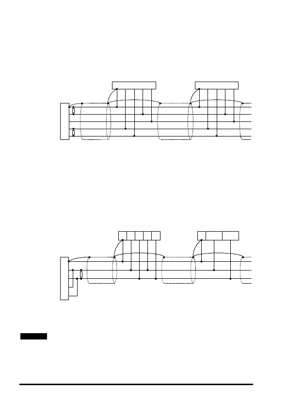
2.5.1 4 Wire RS485 Network
The diagram below shows the connections required for a 4 wire RS485 network,
using a master controller with an RS485 port. The UD70 and MD29 can be
configured to act as master controllers, but this requires DPL programming to
control the network.
An RS232-to-RS485 converter is required to allow a standard PC serial port to
communicatewitha4wireRS485network.
2.5.2 2 Wire RS485 Network
The diagram below shows the connections required for a 2 wire RS485 network,
using a master controller with an RS485 port. The UD70 and MD29 can be
configured to act as master controllers, but this requires DPL programming to
control the network.
An RS232-to-RS485 converter with “intelligent transceiver switching” (also known
as “magic” RS485 converters) is required to allow a standard PC serial port to
communicatewitha2wireRS485network. Anexampleofa“magic”converteris
the MA485F converter from Amplicon.
A “magic” converter is not required is the master contoller has an RTS control
output. This output is enabled when the master is transmitting, and disabled
when the master is not transmitting. Control Techniques software packages
(UniSoft, MentorSoft and SystemWise) do NOT switch the RTS line.
RxARxBTxATxB0V RxARxBTxATxB0V
RxA
RxB
TxA
TxB
0V
Master
UD70, MD29,
Unidrive, Mentor II
Slave
UD70, MD29,
Unidrive, Mentor II
12637 12637
Slave
120Ω 0.25W
termination resistors
TxRxA0V
RxA
RxB
TxA
TxB
0V
Slave
Master
UD70, MD29,
Unidrive
Slave
Commander SE
TxRxBRxARxBTxATxB0V
12637 3 7 2
120Ω 0.25W
termination resistor
NOT E