14
Dynamic Braking
Resistor Connections
The external braking resistor should be connected
to the Unidrive terminals labelled (+) and (-) on the
terminal strip on Unidrive size 1 & 2 or the stud
connections on Unidrive size 3 & 4. The resistor must
be thermally protected in the unlikely event that the
braking transistor fails. This thermal device must either
disconnect the input AC power to the Inverter or
disconnect the resistor from the circuit. Please contact
the a Drive Centre for additional application information.
Custom Resistor Values
The resistor ohmic value is based on the torque
required to stop the motor (and connected load) in the
time dictated by the application. The first equation to
be solved is the torque required knowing the required
stop time.
T = J x N
(Ft - Lb) or
T = 2¹ J x N
(Nm)
t
d x 307 td x 60
Where:
J= Total Inertia (Lb-Ft
2
or Kgm
2
)
N = Motor Max. Speed (RPM)
t
d = Decel Time (Sec.)
T = Torque (Ft-Lb or Nm)
The torque required must be equal or less than 1.5
x motor/drive capability.
HP
(brake) = T x N
or
P(kW) = T x N
5250 30
The ohmic value of the resistor can now be
calculated using the following formula:
R = (V
b)
2
or
R = (Vb)
2
HP(brake) x 746 P(kW)
Where:
V
b = Bus voltage level when braking
= 750 VDC
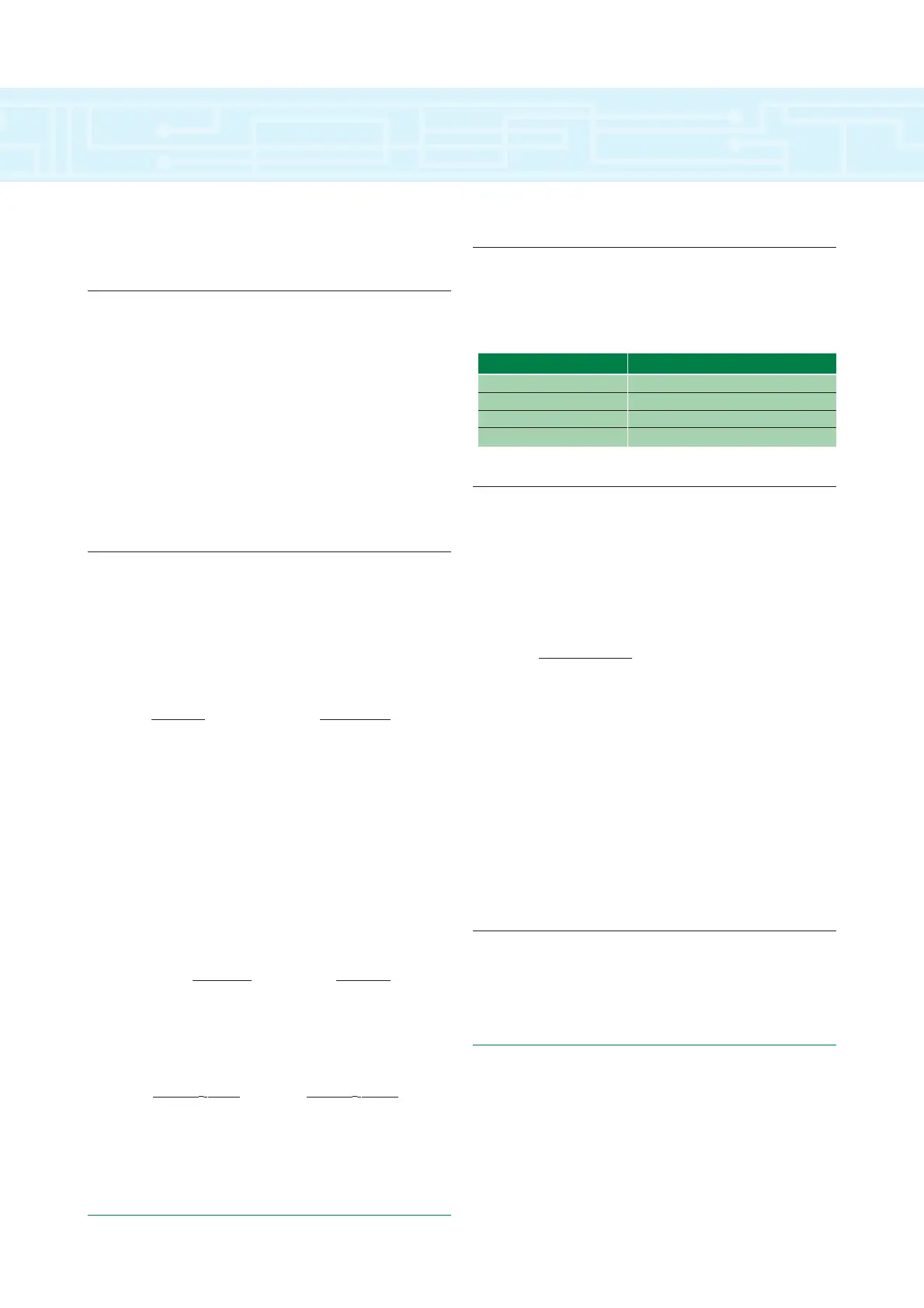
Minimum Values
The calculated minimum ohmic value is limited by
the braking transistor supplied in the Unidrive being
used. The following is a list of the minimum values.
Average Power Dissipation
The average power dissipated in the resistor for
intermittent operation is then simply the number of
watts dissipated per stop times the duty cycle (D).
Where:
D = t
d
td + toff
In order to use this formula for average power
dissipation, the brake resistor must be off long enough
for the temperature of the resistor to return to ambient
temperature between braking cycles. Also, the
maximum on time (or decel time) should not exceed
the peak capabilities of the power resistor. Typically, a
power resistor has the capability of dissipating 10
times rated wattage for 5 to 10 seconds.
Peak Power Rating
The peak power handling ability of the resistor
must meet or exceed the following:
PPK = (Vb)
2
/R
Unidrive Size 1 40 Ohms
Unidrive Size 2 40 Ohms
Unidrive Size 3 10 Ohms
Unidrive Size 4 5 Ohms
MODEL MINIMUM VALUE
drive technical specifications