www.controltechniques.com2
Power Wiring – Sizes 3 to 9A
Heatsink mounted braking resistor
A resistor has been especially designed to mount within the heatsink of
the Unidrive M sizes 3, 4 & 5. The design of the resistor is such that no
thermal protection circuit is required, as the device will fail safely under
fault conditions. On Unidrive M sizes 3, 4 & 5 the software overload
protection is set up at default for the designated heatsink mounted
resistor. If an external brake resistor is used, a thermal overload device is
required. NOTE: The heatsink mounted resistor is suitable for applications
with a low level of regen energy only.
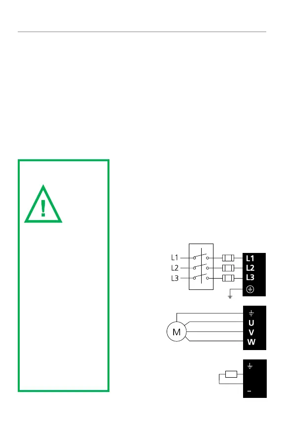
WARNING
For
complete
wiring
and fusing
instructions, refer to
the Unidrive M Power
Installation guide.
*Thermal overload
for braking resistor to
protect against fire risk.
This must be wired to
interrupt the AC supply
in the even of a fault.
This is not required if
the optional heatsink
mounted braking
resistor is used.
Common DC bus connections
*Optional braking resistor
DC
+DC
BR