EasyManua.ls Logo

Controls MVP-101 - User Manual

Controls MVP-101
13 pages
Print Icon
To Next Page IconTo Next Page
Loading...
Product Manual
Part Number: MVP-101
Revision: 2.0
______________________________________________________________________________________________________________________________________
Copyright Controls, Inc.
P.O. Box 368 Sharon Center, OH 44274
Phone 330.239.4345 • Fax 330.239.2845 • www.controlsinc.com
Question and Answer IconNeed help?

Do you have a question about the Controls MVP-101 and is the answer not in the manual?

Summary

Prior to Engine Start

CAN Bus Configuration

Explains J1939 CAN Bus network communication for engine ECU and required source address settings.

Installation Information

Connector Information

Engine Alarms, Codes and Messages

Engine ECU Alarm;De-Rate;Shut Downs

Describes how ECU actions like de-rate or shut down occur due to engine parameters outside normal ranges.

Alarm Annunciation and Code Reader

Explains how the panel displays alarm/trouble codes broadcast by the engine ECU.

Indicator Lamps

Active and Stored Engine ECU Codes

Control Panel Analog and Digital Inputs

Menu System

Menu Navigation and Settings

Details procedures for entering, navigating, exiting the menu system, and changing settings.

Main Menus Overview

Viewing Menus

Lists menu options for viewing engine information, identification, and module details.

Configuration Menus

Lists menu options for controller setup and configuration, requiring a password.

Configuration Menu Details

Quick Setup

Configuration options for engine manufacturer, speed settings, and performance display.

Engine Parameter Configuration

Settings for selecting and configuring engine parameters like speed, temperature, and oil pressure.

Input Configuration

Configuration for analog and digital inputs, including channels and custom messages.

Module Configuration

Settings for pre-alarms, number of starts, and engine speed criteria.

Display Configuration

Options for setting pressure/temperature units and performance display settings.

CAN bus Configuration

Settings for CAN bus communication, including engine manufacturer, addresses, and data transmission.

Maintenance Configuration

Settings for service messages, maintenance schedule selection, and interval warnings.

MOD bus Configuration

Settings for MOD bus communication mode, baud rate, parity, and timeouts.

Overview

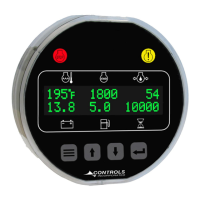
This document describes the MVP-101 controller, a device designed for monitoring and controlling J1939-compliant engines. It serves as a display for engine parameters and alarm codes, and allows for configuration of various operational settings.

Function Description:

The MVP-101 controller communicates with the engine's Electronic Control Unit (ECU) via a J1939 CAN Bus network. This three-wire connection enables the controller to receive and display engine information and alarm codes broadcast from the ECU. A key function of the MVP-101 is to act as a trouble code reader. When the engine ECU broadcasts an SPN.FMI trouble code, the panel illuminates the appropriate LED indicator lamp (Yellow for Alarm, Red for Engine Shut Down), displays the trouble code, provides a code description on the LCD screen, and shows the occurrence count of the code. The panel also provides the ability to check both active and stored engine ECU codes through dedicated menus.

The controller features a display that shows real-time engine parameters such as temperature (e.g., 195°F), RPM (e.g., 1800 n/min), and other values (e.g., 54, 13.8, 5.0, 10000). It includes navigation buttons (up, down, menu, enter) for interacting with the menu system and a "STOP" button, likely for emergency shutdown or engine stop functionality.

The MVP-101 also incorporates analog and digital inputs to monitor additional components, senders, or signals. These inputs can be configured for various purposes, including alarms and shutdowns, expanding the monitoring capabilities beyond standard J1939 parameters.

Important Technical Specifications:

Physical Dimensions:

  • Overall width: 2.44 inches
  • Overall height: 3.81 inches
  • Mounting surface diameter: 3.94 inches
  • Mounting hole requirements (A or B): 2.00 ± 0.03 inches diameter, or 1.94 +0.030/-0.000 inches by 2.03 ± 0.03 inches.
  • Recommended wire exit: 2.38 inches minimum.
  • Wall thickness for mounting: 0.04-0.25 inches.
  • Mounting is secured with a mounting ring/clamp and two 6-32 nuts.

Electrical Connections (Connector A):

  • Pin 1: BATTERY +
  • Pin 2: CAN H
  • Pin 3: CAN L
  • Pin 4: DIGITAL INPUT 1
  • Pin 5: FUEL LEVEL (Analog 1 Input)
  • Pin 6: GROUND

Electrical Connections (Connector B):

  • Pin 1: BATTERY +
  • Pin 2: DIGITAL 1 (Digital Input 2)
  • Pin 3: RS-485 +
  • Pin 4: RS-485 -
  • Pin 5: DIGITAL 2 (Digital Input 3)
  • Pin 6: GROUND

Analog 1 Function Options (Configurable via menu):

  • Fuel Level S-W (Stewart Warner): 240 ohms (Empty) – 33 ohms (Full).
  • Fuel Level VDO: 10 ohms (Empty) – 180 ohms (Full).
  • Oil Pressure 100 PSI (Stewart Warner): 240 ohms (0 PSI) – 33 ohms (100 PSI).
  • Oil Pressure 125 PSI (Stewart Warner): 240 ohms (0 PSI) – 33 ohms (125 PSI).
  • Oil Pressure bar (Stewart Warner): 240 ohms (0 bar) – 33 ohms (7 bar).
  • Oil Pressure VDO PSI: 10 ohms (0 PSI) – 180 ohms (150 PSI).
  • Oil Pressure bar (VDO): 10 ohms (0 bar) – 180 ohms (10 bar).
  • Switch: Allows connection of a switch instead of an analog sender.
  • None: No functionality required.
  • Note: For all sender types, sender ground must be common with battery negative.

Digital Function Activation (Configurable via menu):

  • Off / Always / Run: Defines when the parameter is monitored for alarm conditions (Off disables, Always enables, Run enables when engine is running).
  • Alarm Delay: Time period before an alarm becomes latched after the alarm condition is met.

Usage Features:

Prior to Engine Start:

  • Users must select the proper throttle control mode and parameters for the specific application.
  • The correct SOURCE ADDRESS must be selected in the controller for proper communication with the engine ECU (available in the CAN CONFIGURATION MENU).
  • Enter Menu System: Hold MENU button and press ENTER button.
  • Scroll Menu Options: Press MENU button.
  • Enter Menu: Press UP arrow button.
  • Reverse: Press DOWN arrow button.
  • Exit Menu System: Hold MENU button and press ENTER button.
  • Change a Setting: Press ENTER to bring up brackets [ ], use UP/DOWN arrows to change, press ENTER to make selection.
  • Important: Recycle key to OFF position after changing a setting.

The menu system is divided into "Viewing Menus" and "Configuration Menus." Access to configuration menus requires a password.

Viewing Menus:

  • Active Engine Fault Codes: View/Scroll active fault codes.
  • Stored Engine Fault Codes: View/Scroll stored fault codes.
  • Engine Parameters: View ECU engine information (e.g., % Load, Torque, Oil Temp).
  • Engine Identification: View engine model # and serial #.
  • Module Information: View control unit part # and software version.

Configuration Menus (Password Protected):

  • Quick Setup:
    • Engine Manufacturer (Default: John Deere)
    • TSC Minimum Speed (Default: 650 RPM)
    • TSC Maximum Speed (Default: 2400 RPM)
    • Performance Display (Default: Off)
  • Engine Parameter Configuration:
    • Parameter Selection (Speed, Coolant Temp., Oil Pressure, Fuel Level, Voltage, Hour Meter)
    • Parameter Setup (Varies based on parameter)
  • Input Configuration:
    • Configure Parameter (Channels, Custom Message)
    • Digital Input 1, 2, 3 Configuration
  • Module Configuration:
    • Pre Alarms Displayed (Default: 4)
    • Clear Number of Starts (Yes/No)
    • Engine Run Speed Criteria
    • Engine Stop Speed Criteria
  • Display Configuration:
    • Pressure & Temp Units (English/Metric)
    • Performance Display On/Off
  • CAN bus Configuration:
    • Engine Manufacturer (John Deere)
    • TSC1 Address (Default: 3)
    • Source Address (Default: 44)
    • Engine Address (Default: 0)
    • Fuel Level Transmit
    • Voltage Transmit
    • Hours Transmit
    • Engine Status Transmit
    • Panel Status Transmit
    • Panel Information Transmit
    • Faults Transmit
    • Text During Sleep
    • JDLINK Auto Accept
  • Maintenance Configuration:
    • Services Messages (Yes/No)
    • Maintenance Schedule Selection (A-C)
    • Schedule Reset (Yes/No)
    • Schedule Interval (Default: 1000 hrs.)
    • Schedule Warning (Default: 10 hrs.)
    • Schedule Trip (Default: 0 hrs.)
    • Schedule Message
  • MOD bus Configuration:
    • Mode Off/Slave/Gauges
    • Baud Rate
    • Parity
    • Stop Bits
    • Slave Address
    • Communication Timeout

Maintenance Features:

The Maintenance Configuration menu allows for setting up service messages and maintenance schedules. Users can define schedule intervals, warnings, and trip points, as well as reset schedules. This helps in proactive maintenance planning and ensures timely servicing of the engine and associated components. The "Services Messages (Yes/No)" option suggests the ability to enable or disable maintenance-related notifications.

Controls MVP-101 Specifications

General IconGeneral
BrandControls
ModelMVP-101
CategoryControl Systems
LanguageEnglish