Do you have a question about the Cooke & Lewis CLVHS50 and is the answer not in the manual?
Installation requires a qualified person; beware of electric shock.
Check package, decide location, handle with care.
Notes on fuel appliances, specs plate, and manual handover.
Choose between external extraction (A) or internal recirculation (B).
Install on wall or under cupboard. Beware of sharp edges, use gloves.
Mark 4 wall positions per diagram, ensure appropriate fixings.
Check wall for hidden pipes/cables before drilling.
Drill 4 holes (6mm), insert plugs and screws.
Mount appliance to wall using specified fixings and screws.
Use specified fittings/screws to avoid electrical hazards.
Attach hood unit to mounting structure using screws.
Ensure all screws are fully tightened.
Install under cupboard, ensuring correct hole size.
Diagram shows main dimensions for installation.
Diagram shows installation of specific components.
Install VENT PACK (Ø125mm) for ducted extraction.
Install components [05] and [04] for recirculation.
Diagram shows the completed recirculation setup.
Connect directly to mains via circuit breaker.
Class II appliance, must NOT be earthed.
EUR and UK wiring configurations shown.
Read instructions before using the appliance.
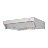
Details of control panel and recommended usage.
Step-by-step guide on how to replace the lamp.
Instructions for replacing carbon filters every three months.
Procedure for cleaning grease filters monthly.
| Brand | Cooke & Lewis |
|---|---|
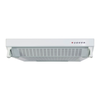
| Model | CLVHS50 |
| Width | 50 cm |
| Number of Fan Speeds | 3 |
| Color | White |
| Filter Type | Aluminium Grease |