EasyManua.ls Logo

Cooper McGraw-Edison VR-32 User Manual

Cooper McGraw-Edison VR-32
91 pages
To Next Page IconTo Next Page
Page #1 background imageLoading...
Page #1 background image
Contents
General . . . . . . . . . . . . . . . . . . . . . . . . . . . . . . . . . . . . 1
Safety . . . . . . . . . . . . . . . . . . . . . . . . . . . . . . . . . . . . . . 2
Receiving, Installation and Maintenance . . . . . . . 1-1
Control Basics . . . . . . . . . . . . . . . . . . . . . . . . . . . . . 2-1
Control Function Codes . . . . . . . . . . . . . . . . . . . . . 3-1
Control Advanced Features . . . . . . . . . . . . . . . . . . 4-1
Tap Changer. . . . . . . . . . . . . . . . . . . . . . . . . . . . . . . 5-1
Troubleshooting Guide . . . . . . . . . . . . . . . . . . . . . . 6-1
Accessories . . . . . . . . . . . . . . . . . . . . . . . . . . . . . . . 7-1
Spare Parts. . . . . . . . . . . . . . . . . . . . . . . . . . . . . . . . 8-1
Index . . . . . . . . . . . . . . . . . . . . . . . . . . . . . . . . . . . . . 9-1
General
McGraw-Edison
®
VR-32 voltage regulators are
regulating auto-transformers. They regulate rated
voltage from 10% raise (boost) to 10% lower (buck) in 32
approximately
5
/
8
percent steps.
McGraw-Edison regulators are supplied with the
following standard features:
Dual-rated 55/65°C rise
ADD-AMP™ capability
Unit construction
Sealed-tank construction
Pressure relief device
• 17” minimum creep bushings with clamp-type
connectors
MOV-type external series arrester
Shunt arrester mounting bosses
Two laser-etched nameplates
Oil sight gauge
Upper filter press connection
Drain valve and oil-sampling device
CE mark compliant control
Control cable quick disconnect
The 65°C rise insulation system and the sealed-tank
construction allow for a bonus capacity 12% above the
55°C nominal rating without loss of normal insulation
life. The bonus capacity is stated on the nameplate
(such as 167/187 kVA for a nominal 167 kVA regulator).
All McGraw-Edison regulators are manufactured and
tested to ANSI standard C57.15.
Unit construction, which suspends the internal assembly
from the cover, allows for ease of inspection and
maintenance.
There are three types of step-voltage regulators: source-
side series winding (Type B), load-side series winding
(Type A), and series transformer. McGraw-Edison
regulators are usually equipped with an equalizer
winding. The nameplates located on the tank and control
box define the power circuit.
Voltage Regulators
McGraw-Edison
®
VR-32 Regulator and CL-5 Series
Control Installation, Operation and Maintenance
Instructions and Parts Replacement Information
S225-10-10
October 2001 • Supersedes 12/00 • © 2001 Cooper Power Systems, Inc.
Printed in U.S.A.
These instructions do not claim to cover all details or variations in the equipment, procedure, or process described, nor to provide directions for
meeting every possible contingency during installation, operation or maintenance. When additional information is desired to satisfy a problem not
covered sufficiently for the user’s purpose, please contact your Cooper Power Systems representative.
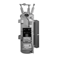
Figure 1.
VR-32 Voltage Regulator with CL-5 Series Control
Service Information
Question and Answer IconNeed help?

Do you have a question about the Cooper McGraw-Edison VR-32 and is the answer not in the manual?

Cooper McGraw-Edison VR-32 Specifications

General IconGeneral
CategoryController
TypeVoltage Regulator
ModelVR-32
ManufacturerCooper McGraw-Edison
Frequency60Hz
PhaseSingle

Summary

Safety Information

Safety Instructions

General safety guidance and procedures for operating and maintaining the regulator.

Hazard Statement Definitions

Explanation of hazard symbols (Danger, Warning, Caution) used in the manual.

Receiving, Installation and Maintenance

Receiving Inspection

Procedures for inspecting the regulator shipment for damage and shortages.

Pre-Installation Inspection

Checks to perform on the regulator before connecting it to the line.

Systems Connections

Determining of Leading or Lagging

Method to identify phase shift for delta connections to ensure correct regulator configuration.

Regulator Installation and Service

Placing a Regulator in Service

Steps for connecting and energizing the regulator without interrupting load.

Setting the Control for Service

Procedure for programming the regulator's control system parameters.

Accessing the Control

How to access control settings and activate security levels.

Control Configuration and Operation

Setting the Controls for Basic Operation

Configuration of key parameters like voltage, bandwidth, and time delay.

Control Operating Modes

Selecting how the control responds to voltage deviations (Sequential, Time Integrating, Averaging).

Reverse Power Operation

How the control logic handles bidirectional power flow.

Front Panel Components

Lower Section - Grey

Description of controls in the lower part of the regulator control panel.

Upper Section - Black

Description of the LCD display and keypad interface.

Operational Checks and Calibration

Operational Check

Procedures to verify control and regulator functionality.

Voltage Calibration

Process for calibrating voltage measurement accuracy on the control.

Current Calibration

Process for calibrating current measurement accuracy on the control.

Troubleshooting Guide

The Regulator Will Not Operate Manually or Automatically

Diagnosing issues where the regulator fails to operate.

Control Troubleshooting

Steps for diagnosing problems within the regulator control system.

Junction Box Troubleshooting

Specific troubleshooting steps for the junction box components.

Tap Changer Mechanics and Operation

Tap Changer Operation

Overview of spring-drive, direct-drive, and quik-drive tap changer types.

Contacts

Description of contact structures, materials, and wear limits.

Spring-drive Operating Sequence

Step-by-step explanation of the spring-drive tap changer mechanism.

Digital Communications

Digital Communication Interface Board

Information on interface boards for SCADA connectivity.

Data Retrieval and Settings Uploading

Using Data Reader and PC software for data management.

Spare Parts

Ordering Information

Required information for ordering replacement parts and accessories.

Related product manuals