1
Enlarged View
Lower
Abutement
Switch
Assembly
PLEASE NOTE: This model is designed
for use with Walthers Code 83 Bridge
Track with Separate Approach Ends
(#948-886, sold separately), which can
be installed during this step for easier
construction.
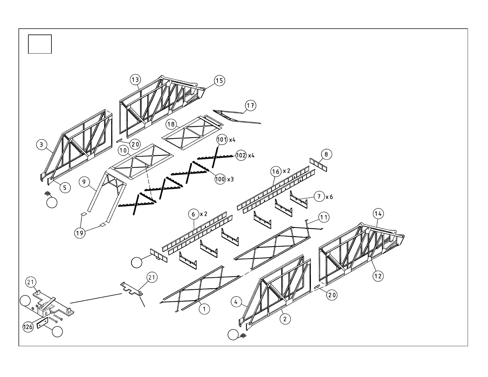
1) With the alignment tab along a straightedge (tabs point to the ends), make two Girders by gluing Short (6) and Long
(16) sections lengthwise as shown; set this assembly aside to dry completely. Glue notches in Girder assemblies to open-
ings in Cross Girders (6x 7). Continue assembly by gluing Right End Girder (8) to the pivot (right) end. Note the tab on
Left End Girder (#128) is at the bottom: complete assembly by gluing to left end as shown; set aside to dry.
2) Glue Left (3 & 5, 13 &15) and Right Side Girder Halves (2 & 4, 12 & 14) together. PLEASE
NOTE: Glue Splice Plates (2x 20; one per side) to lower edge of each pair of sides as shown,
making sure they are all the way up and in the slot so they will not interfere with bottom bracing.
Set this assembly aside to dry.
3) Glue Top Girder Halves (10, 18) together lengthwise as shown. Insert the four
Latticework sections (one each #101, 102) to form an X-shape; the joint will
need to be fitted to accommodate the angle. Glue the Single Latticework
Sections (3x 100) to the Top Girder assembly as shown. Align the ends of the
X-shaped Latticework (assembled from parts #101 & 102) and adjust as needed
so parts fit square and snug, and apply a little glue where parts meet.
4) Align ends of Cross Girder assembly with right and
left Side Girder assemblies and glue in place. Fit and
glue Top Girder assembly in position. Glue Portals
(9, 17) to ends of Side Girders. Glue End Caps (4x
19) to Side Girders as shown. Glue Bottom Bracing
(1, 11) to underside of Girder assembly.
5) PLEASE NOTE: For a nonworking model only,
glue Bridge Shoes (2x 200) to pins on Side Girders
as shown. For a working model, you’ll need to
assemble the Lower Abutment Switch for later instal-
lation atop a bridge abutment
or pier (both sold separately):
final installation and
127
128
97
alignment are covered
in Walking Beam
Support Assembly step
9. The Switch Holders
(Right 126 and Left
127) are mirror images;
be sure the extended
“wings” are glued to the
top of the Abutment
Plate (21) as shown. Insert the Micro Switch
between the Holders, along with the Filler
Piece (97); adjust the fit as needed and secure
in place with 16mm Long Machine Screws and
Nuts as shown. Set aside for final assembly
steps.
200
200