5
DECALING
1. After cutting out the decal, dip in water for 10 seconds, remove and let stand for1 minute. Slide
decal onto surface, position and then blot off any excess water.
2. Lightly brush Micro Sol® on top. This will soften the decal allowing it to con-form to irregular
surfaces. DO NOT TOUCH DECAL while wet!
3. When the decal is thoroughly dry, check for any trapped air bubbles. Prick them with the point of
a small pin or hobby knife blade and apply more Micro Sol®.
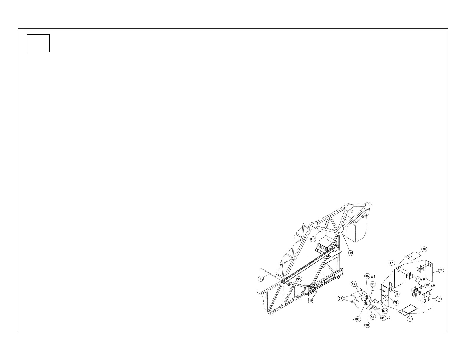
22) PLEASE NOTE: To improve the fit of the metal pins (2x #119 cut in step 2), we suggest drilling a #48 hole in each Walking Beam Support mounting point and a #47 hole at each of the
four Walking Beam openings.
23) Insert metal pins (4x 119; two per assembly) to connect the A-frames to the bridge, and Walking Beam assembly to the top of the A-frames. Drill a #48 hole through the openings in
the racks, bridge and supports, and thread the Long Metal Rod (114) through these openings.
PLEASE NOTE: Before attaching the gear racks for final assembly, place the entire bridge on a flat, level surface so that all gears and gear racks will be in alignment.
24) Place - do not glue - Gears (4x 116; two per side) on shafts molded Inside Left (46) and Right (47) Gearbox Half (2x 46); make sure these mesh with the gear on the motor shaft and that the gears
turn easily on the gearbox half pins
25) Note the correct placement of the Gear Racks assembled in step 17 (right side shown); the open connection points face forward while the stops (raised round areas molded on the rack sides) are
at the rear towards the counterweight. Be sure the tab on the Left Gear Rack aligns with the Cabin Micro Switch arm. Place the Right and Left Gear Rack assemblies on the gearboxes.
26) Attach the Rack Ends to the Moveable Bridge Rod (114) with the End Cap Pins (2x 95).
27) Place the completed Rack assemblies with the teeth facing down on the gears; confirm that all gears on the gearboxes and racks align and fit freely. Carefully glue the edges of the Outside Gear
Box Halves (2x 48) to the edges of the Inside Gear Box Halves and let dry completely.
28) PLEASE NOTE: To facilitate raising and lowering the bridge, add approximately five ounces (141.7g) of weight (not included) such as BBs or sand inside the counterweight assembly; after the weight
is installed, glue Counterweight Top (68) and Hatch Cover (69) in place.
29) Apply a small amount of plastic-compatible grease (sold separately) to the Worm Gear on the motor shaft, and a drop of plastic-compatible oil (sold separately) to the other rotating parts.
30) Connect the motor wires to a transformer - PLEASE NOTE: do not exceed 6 Volts DC during operation: although not automatic, you can manually raise and lower the bridge using the direction lever
on the transformer, and you can stop and reverse direction of the bridge at any time. Carefully test the operation of the Cabin Micro Switch to stop the bridge in the “up” position.
31) Install the Lower Abutment Switch assembly on top of an abutment or pier (both sold separately), making sure it aligns with the “feet” at the end of the side girders when the bridge is in the down
position. Adjust the switch to turn off the motor just as the movable span touches down – be careful not to force the span too far and stall the motor. Test the operation; PLEASE NOTE: the motor must
shut off completely when the bridge reaches the up or down positions to prevent damage to the mechanism. Tighten the contact screws on both switches once you’re satisfied with the bridge operation.
The Cabin Sides (36, 37, 38) can be glued in place; the Shed Roof should be set in place so you can remove it to make adjustments or perform future maintenance.
Interlocking Tower Assembly
32) Glue Windows (79) and Doors (81) to Walls (74, 75, 76, 77). Using the raised ridge on the Base (73) to align parts, glue
Walls to Base and at inside corners where parts meet.
33) Glue Stairs (2x 83) to top of Large Platforms (2x 86). Glue Stairs (83, 84) to top of Small Platforms (2x 85) as shown.
Note the molded ledges on Left Tower Wall (75); glue the Large Platforms on top of the ledges and below the doors. To
prevent breakage, glue Long Handrail (90) to the inside of the Stairs on both Large Platforms at this time. Glue Small
Platforms to ledges on the right of the Wall; make sure Long Stairs touch Base.
34) PLEASE NOTE: Glue Outside Railings (2x 89) to the outside of the Platforms; Glue Railings 87 and
87A to the top of Platforms and to the Wall. Glue Inside Railing (88) to Wall and to Long Handrail (90).
35) Tower Roof (78) may be glued, or set in place if you wish to add lights or interior details (sold
separately).
2
 Loading...