2
Diode
Cabin Micro Switch
Diode
Motor
Abutment Micro Switch
to power source
6 volts DC
DPDT Reversing Switch
Cabin & Drive Subassembly
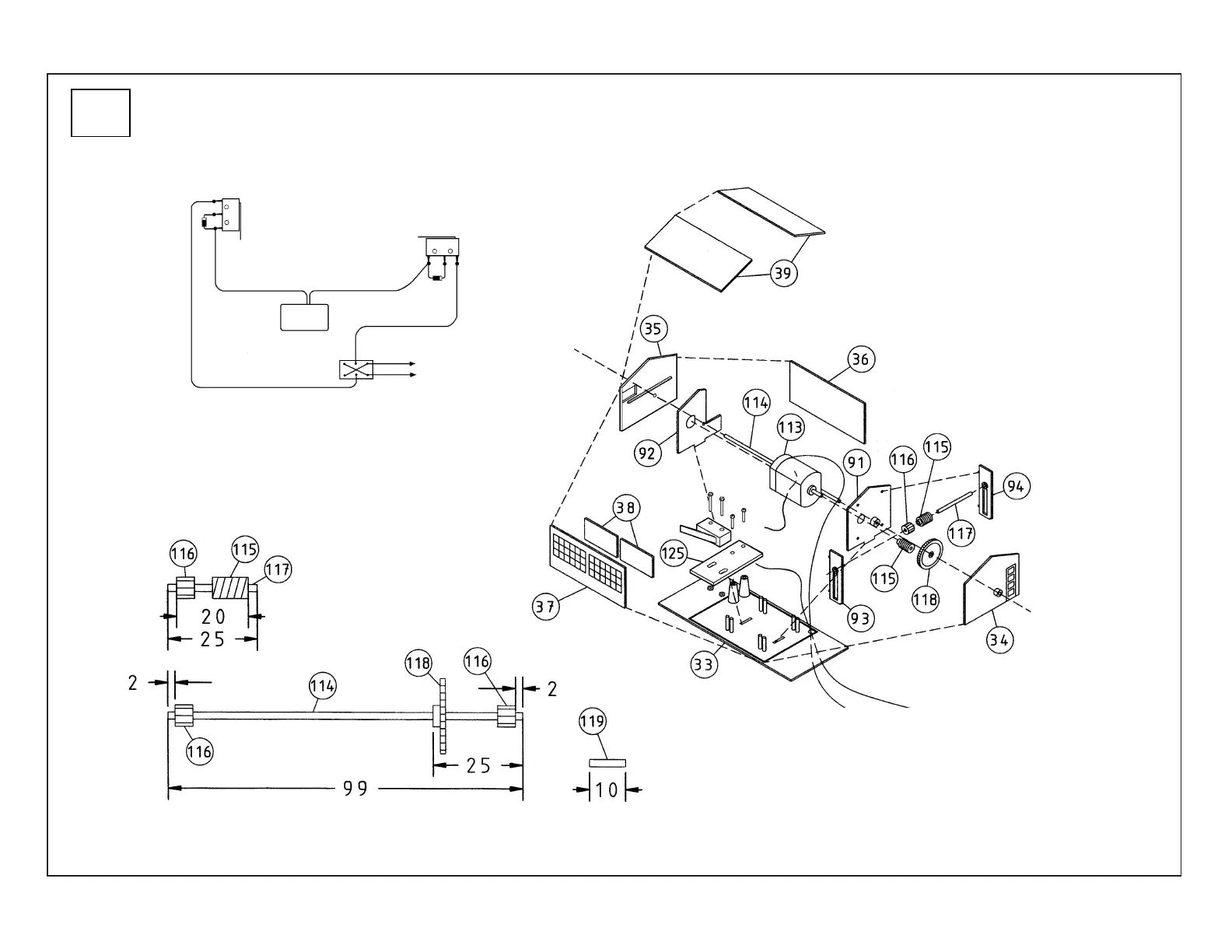
Drive and Wiring Assembly Diagram
6) Note the correct placement of all components on the motor wiring diagram below; the light
colored area on each diode indicates its proper orientation. We suggest using a double-pole,
double-throw reversing switch (sold separately) to turn the motor on and off. Use a DC power
supply (sold separately) that can be adjusted to about 6 volts.
7) Using the metal rod provided, cut drive shafts to these lengths and lightly
bevel the ends:
2x #114: 3.8" (99mm) each
1x #117: 0.9" (25mm)
6x #119: 0.3" (10mm) each
8) On the end opposite the wires, press a Worm Gear (115) on the
Motor (113) shaft. PLEASE NOTE: Cut the other end of the shaft
so it’s about 1mm long; if using a power tool and cutting disk, wear
proper safety gear and work carefully; do not overheat the shaft!
9) With the Cabin Micro Switch all the way at the ends of the slots,
attach the Switch to the Platform (125) with the 16mm Long
Screws and Nuts. Cut two pieces of wire about 4" (10.1cm) long
and a single piece 2" (5cm) long to prewire the Cabin; solder wires
to Motor, and solder wires and diodes to Cabin Micro Switch as
shown on the wiring diagram.
10) Assemble Short Drive Shaft (117) as shown with
Large (115) and Small (116) Gears inset 0.09"
(2.5mm) from each end.
11) PLEASE NOTE: Small Gears (2x
116) as shown are installed in a later
step. Press Large Gear (118) on to
Shaft (114), 0.9" (25mm) from the end;
Slide Shaft through small holes in Right
(91) and Left (92) Motor
Mounts and End Wall
(35); the Large Gear will
rest near the Right Motor
Mount. Slide Shaft
through small holes on
opposite End Wall (91).
12) Slide Left (93) and Right (94) Short Shaft Supports onto ends of Short Shaft assembly as
shown. Using the pins to align parts, glue Shaft Supports into openings on Right Motor Mount
(91). Note the raised ridge on the Floor; align slots on inside of Right Cabin Wall (34) with
edges of Short Shaft Supports and raised ridge on Floor and glue in place.
13) Glue Glass (2x 38) to inside of Front Cabin Wall (37). Using raised ridges on Floor (33)
to align parts, glue Front, Left (35) and Rear (36) Cabin Walls to raised ridge on Floor and at
inside edges where parts meet. Roof Halves (2x 39) may be glued together where parts meet
in the center or left as separate parts. PLEASE NOTE: We suggest you set aside the front
and back Cabin Walls and Roof for later assembly after your Bridge is in place and the
moveable span is adjusted on your layout.