| Page 11
ONE SD-LAN Head
End Equipment
Quick Installation Guide
SD-LAN-000-HEEQUIP
Qucik Installation I SD-LAN-000-HEEQUIP
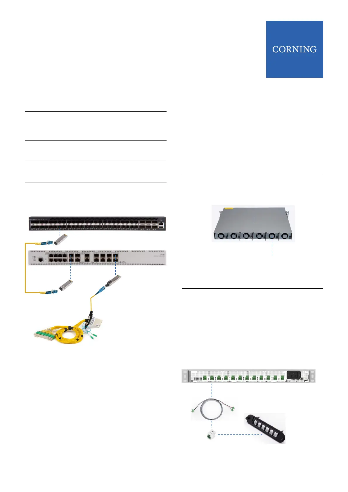
Step 6 Using an LC/UPC – LC/UPC Duplex
jumper, connect the SFP in the TOR
switch to the SFP in the OLT
Step 7
Step 8
Step 9
Insert a ber PON SFP into one of
the PON output ports on the OLT
Connect an SC/UPC connector
jumper to the Fiber PON SFP
Plug the other end into ber patch
panel that connects the ber link to
an Optical Splitter
Step 5
Insert the appropriate SFP into
available port on OLT
7 Power Set Up |
NOTE: For detailed instructions on mounting and
installing PSU6 see Coring Quick Installation Sheet
CMA-477AEN.
NOTE: The DE2-CCA-1PR18-2M assembly is used for
729x 4 port model ONT’s.
The DE2-CCA-2PR18-2M assembly can be used to
feed 2 Micro 8293 ONT’s
Step 2
Step 1
Insert selected quantity of power
supply modules (PSM-I) into back of
unit
Mount PSU6 in Head End equipment
rack
PSM-I
Step 3
Step 4
Plug power cord into PSU6 unit and
connect to power source
Insert power cross connect
assemblies (DE2-CCA-1PR18-2M or
DE2-CCA-2PR18-2M) into front
power ports and connect to selected
power feeds on patch panel
Power Cross
Connect Assmblies
7.1 PSU6 Connections