SpiderCloud Radio Node - SCRN-340 Hardware Installation Guide
11
Radio Specifications
The SCRN-340 has the following variants:
Ports
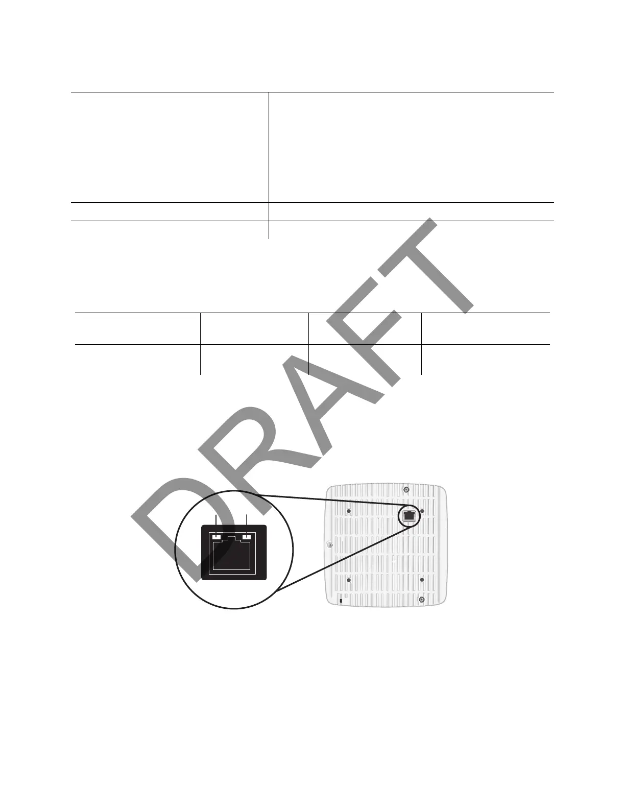
The radio node has one 1 Gigabit Ethernet port that supports a Category 5e (Cat 5e) or better twisted-pair
cable with an RJ-45 connector. Figure 6 shows the Ethernet port. There are two LEDs on the connector:
• Link: Steady green state indicates a normal Layer 2 link connection has been established.
• Activity: Yellow blinking indicates data activity.
Figure 6 Ethernet Port
EMC/Radio(FCC)
FCC Part 15B (Class A)
FCC Part 15 Class A
FCC Part 24
FCC Part 27
FCC 47 CFR 1.1307(b)
FCC 47 CFR 1.1307(b)
Agency/Marking TUV Rheinland
RoHS Directive 2011/65/EU
Table 5: Radio Node Specifications
RadioNodeModel
Operating Mode Network Listen Bands
Maximum Transmit Power
(per Band)
SCRN-340-02041314 and
SCRN-340-02041314-EQ
LTE Band 2/25, 4(66),
13 and 14
LTE bands 25, 66, 13,
and 14
27 dBm LTE licensed band
Table 4: SCRN-340 Compliance (continued)