SpiderCloud Radio Node - SCRN-340 Hardware Installation Guide
19
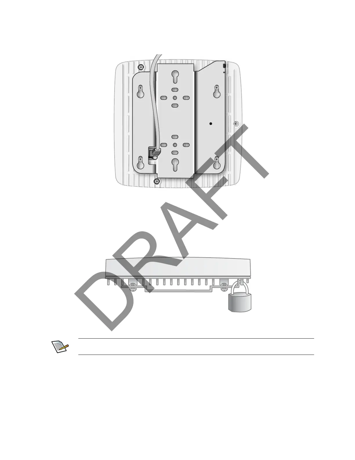
Step 2 Insert the RJ-45 connector through the rectangular bracket opening into the Ethernet port as
shown in Figure 15:
Figure 15 Route and Terminate the Cable
Step 3 Insert the radio node into the mount bracket.
Completing the Installation
Step 1 Attach a padlock or cable tie wrap into the provided slot to secure the unit to the mount
bracket.
Figure 16 Padlock and Lock Holes
Step 2 The radio node boots up and attempts to connect to the services node. Refer to Boot
Sequence and Services Node Communication on page 20 for more information.
The lock in the above figure is shown schematically. The orientation is for illustration purposes
(not accurate) since the bracket is typically wall or ceiling mounted.