SpiderCloud Radio Node - SCRN-340 Hardware Installation Guide
13
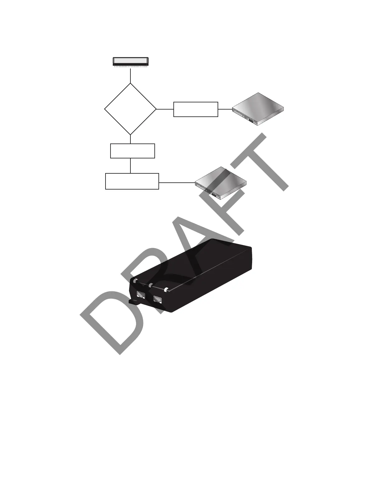
Figure 8 shows the valid radio node cabling/powering options:
Figure 8 Valid Radio Node Cabling/Powering Options
The illustration below shows a generic single-port PoE+ injector. Use this injector only when a PoE+ Ethernet
switch is not available.
Figure 9 Typical PoE+ Injector
To connect the PoE+ injector to a radio node
Step 1 Attach the injector power cord to a power source.
Step 2 Connect an unpowered Ethernet cable from a switch to the IN port on the injector.
Step 3 Connect an Ethernet cable from the injector’s OUT port to the radio node. The injector will
now inject power onto a blue and brown wire pairs in the cable. The radio node will expect a
nominal 48V DC input (57V max) from a typical PoE+ injector.
Services Node
PoE+ Switch
Out
In
Services Node
PoE+ Switch or
PoE+ Injector
PoE+ Injector
Non PoE+ Switch
OUT
IN
CONNECT
PoEPLUS
ON