Package Contents
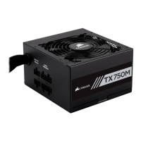
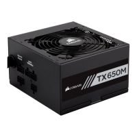
• Corsair TX650W/TX750W Power Supply unit
• User Manual
• AC Power cord
• Cable ties
• Mounting screws
• Corsair case badge
Corsair Cable Configuration
• 1 x 610mm (24”) 24-pin ATX power connector cable.
Note: The ATX power connector has a detachable 4-pin mechanism in order
to support either a 24-pin or a 20-pin socket on the motherboard.
• 1 x 610mm (24”) 8-pin EPS12V connector cable.
Note: The EPS12V power connector has a detachable 4-pin mechanism
in order to support either an 8-pin socket or a 4-pin “P4/12V” socket on
the motherboard.
• For TX650W: 2 x 610mm (24”) 6+2-pin PCI-E connector cable.
• For TX750W: 4 x 610mm (24”) 6+2-pin PCI-E connector cable.
• 2 x 864mm (34”) SATA connector cable with four SATA connector heads.
• 2 x 1016mm (40”) 4-pin peripheral power connector cable with four connector
heads and one small 4-pin for floppy drive.
5