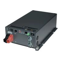
3-5-1. Connect the cables to the power input terminals on the rear panel of
the inverter. The red terminal is represents positive (+) and black
terminal represents negative (-). Insert the cables into the terminals
and tighten the screw to clamp the wires securely.
Also, use only high quality copper wire and keep cable length short, a
maximum of 3 - 6 feet.
WARNING!
The installation of a fuse must be on a positive cable.
Failure to place a fuse on “+” cables running between
the inverter and battery may cause damage to the
inverter and will void warranty.
WARNING!
Ensure all the DC connections are tight (torque
to 9 – 10 ft-lbs, 11.7 – 13 Nm). Loose connections
may cause overheat and fire.
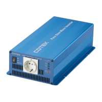
AWG#2 - #6
Battery to inverter cable connection
Do not place anything between
battery cable lug and terminal surface.
Assemble exactly as shown.
18