9For additional information email info@ardisam.com or call 800-345-6007 M-F 8-5
Operator’s Manual
20969 CRT Tiller
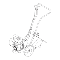
UPPER
HANDLE
BAR
LOWER
MOUNT
HANDLE BAR
EXTENSIONS
17459-0011R1
UNPACKING AND ASSEMBLY
Your rototiller comes fully assembled except for a few parts.
The following instructions will help you unpack your tiller and
assemble and adjust your tiller’s depth regulator lever, cable
tension and handle bar height. You will need one 16 mm and
one 17 mm wrench.
Carton Contents:
• Rear Tine Rototiller w/Handle Bar
• 2 - Side Shields
• 2 - Wheels
• Depth Regulator
• Parts Bag
Tools Required for Assembly:
16 mm & 17 mm wrenches
Unpack:
1. Open top of carton and remove handle bar assembly.
2. Find parts packet. Parts packet contains:
• M10-1.5 x 45 mm hex head bolts
• M10-1.5 x 25 mm hex head bolts
• M10-15 mm nylock nuts
• M10 at washers
• M6-1 x 12 mm hex head bolts
• M6-1 nylock nuts
• 1 - Lock pin
• 12 - M6 at washers
• 2 - Handle bar extensions
NOTE: Parts packet also includes Engine Manual,
Warranty Registration Card and this Operator’s
Manual.
3. Cut open seems of carton, exposing all contents and
remove machine by:
a. Attaching loose wheels in box onto machine with
wheel lock pins in free-wheel position. Slide wheel all
the way onto the axle and insert lock pin through the
axle hole only. (SEE OPERATION SECTION)
b. Roll tiller from carton.
FIGURE 2
Assembly:
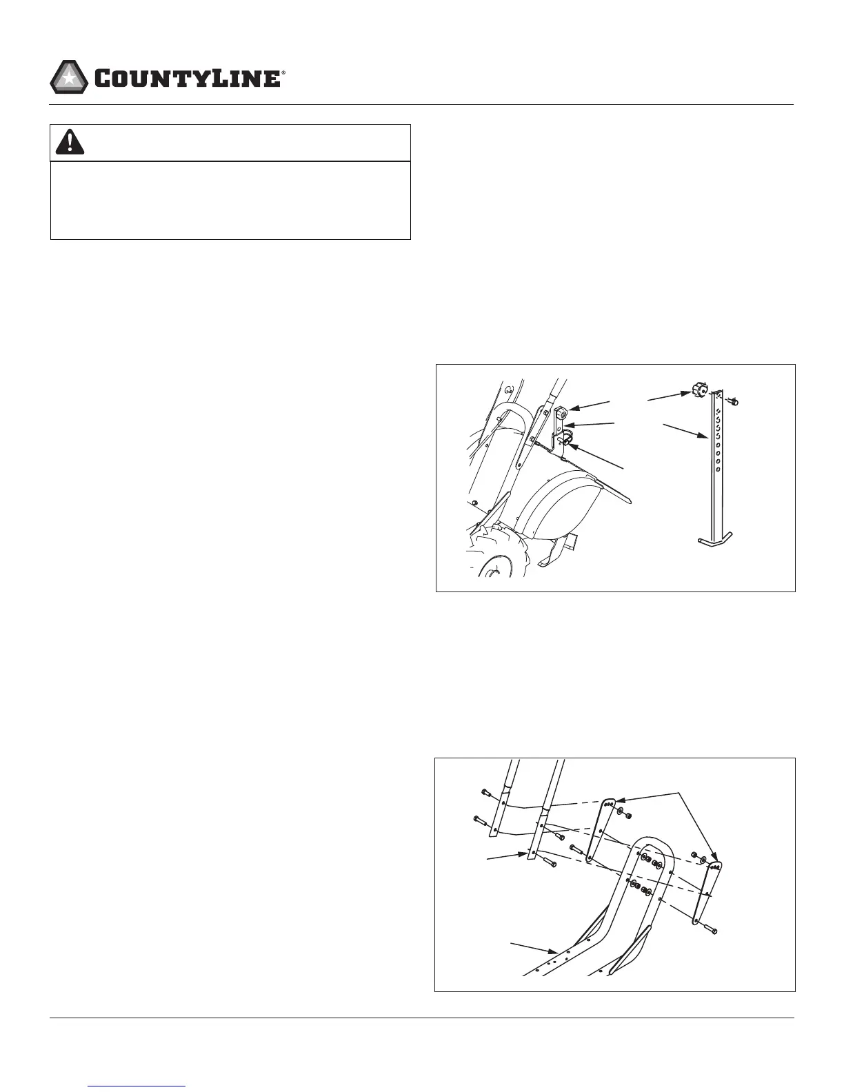
Install Depth Regulator:
1. Locate depth regulator and lock pin. SEE FIGURE 1
2. Unscrew adjusting knob from the top of the depth
regulator and slide depth regulator up into vertical slot at
the rear of the tine shield. SEE FIGURE 1
3. Reattach the adjusting knob to the top hole of the depth
regulator.
4. Insert lock pin through the hole in the vertical slot and a
hole in the depth regulator to hold it in place.
Attach Handle Bar
1. Locate handle bar extensions. SEE FIGURE 2
2. Place handle bar extensions on outside of lower handle
bar mount. Line up the handle bar extension pieces
with the lower handle bar mount as shown in the decal
located on the lower handle bar mount next to the
mounting location. SEE FIGURE 2
DEPTH
REGULATOR
KNOB
LOCK PIN
17459-0007R1
FIGURE 1
DO NOT TRY TO LIFT THE TILLER FROM THE
SHIPPING CARTON. THE TILLER IS HEAVY AND
CAN CAUSE INJURY. USE TWO PERSONS WHEN
LIFTING THE TILLER.
WARNING