Electrical Wiring and Bonding
The automatic cover system must be bonded to meet the National Electrical Code. Bond both tracks to the mechanism by
attaching a bonding lug to the guide feed screw and running a #8 solid copper bond wire to the mechanism.
Bond the lid to the mechanism by drilling a hole in the lid at either end and attaching a bonding lug. Run bond wire from this lug
to the mechanism.
All brackets and any other metal over 4” long should likewise be bonded to the mechanism. There should be a bond wire
extended from the equipment pad to the cover box, so it too can be attached to the mechanism.
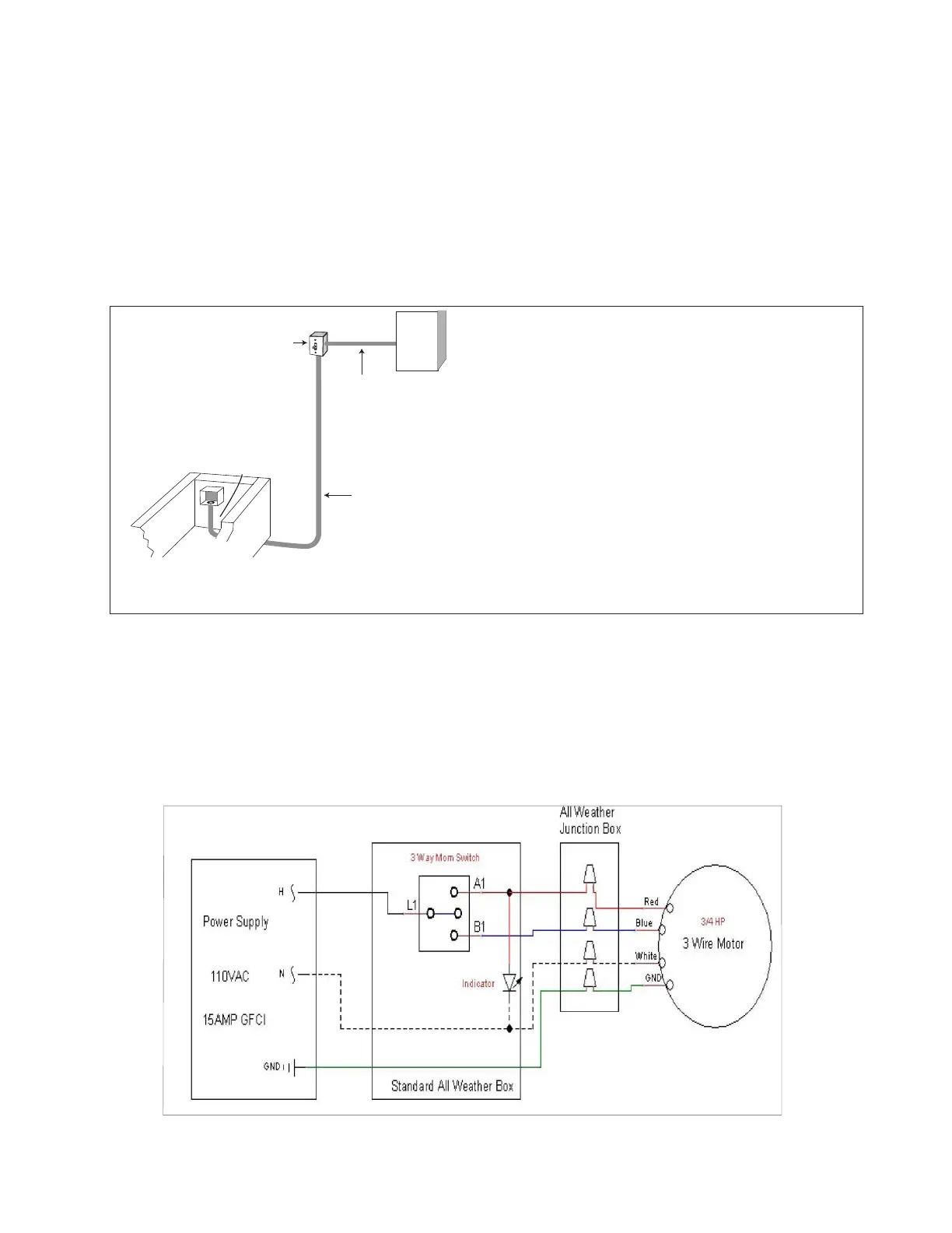
Note: Builder is responsible to bring proper electrical lines, conduit and bonding to the mechanism. Electrical
wiring diagram and details are shown below.
Wiring the Electrical Switch
The control switch must be mounted in an all-weather box, in a location where 100% of the pool is visible.
Connect the control switch according the diagram below.
© Latham Pool Products, Inc. 2019. All rights reserved.
#8 bond wire
Conduit with 4 wires
(2 directional wires, neutral &
unbroken ground)
Single gang all-weather box mounted on
corner of end wall of cover vault approx. 3”
from top of deck.
Key switch is mounted in a standard all-weather
UL listed, single gang box. The box must be
mounted 60 inches off the ground and in a
location where 100% of the pool is visible.
It is recommended that this switch be mounted
halfway along the side of the pool, and within 12
ft of the waters edge.
Conduit with 3 wires
(hot, neutral & unbroken ground)
Note: wires must be sized to meet all
applicable codes. Motor draws 8.8 amps.
Sub-panel with
dedicated
110 Volt,
15 amp breaker
and GFCI
Ground Fault Circuit Interrupter
A GFCI must be used in the electrical supply line for the motor.
This should be on a separate dedicated circuit only for the pool cover.
Key Switches
Mount a standard, single gang, all-weather junction box for the key switch at a
point where 100% of the pool is visible. This is a mandatory requirement to meet
ASTM safety standards. The key switch should not be placed in the mechanism
box. This does not meet UL code.
Options
Coverstar has several different wiring options that include limit switches
wireless remote control, water feature shutoffs, etc. See your Coverstar
distributor for details.
Running Wires
Bring 110V to the key switch. From the panel to the key switch, run 3 wires
(hot, neutral & unbroken ground). From the key switch to the motor end of
the housing, run 4 wires (2 directional, a neutral and an unbroken ground).
Terminate the wires in a weather tight “J” box. The motor is 110V, 3/4 HP
with full load amperage of 8.8 amps. Follow all applicable codes regarding
wire size, grounding, connections, etc.