page 8
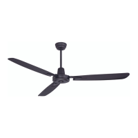
9. Light Kit Assembly (Optional). (cont.)
LED light kit
LED light kit
glass shade
motor
housing
fitter plate
Carefully arrange wiring within fitter plate. Align
slotted holes in LED light kit with loosened screws
in fitter plate. Twist LED light kit to lock. Re-insert
screw that was previously removed and tighten all
3 screws securely.
To attach glass shade, align grooves on glass
shade with nodules on inside of LED light kit. Push
up gently on glass shade and then turn glass
shade to the RIGHT (clockwise) until it no longer
turns.
NOTE: Pull down VERY GENTLY on glass shade to
make sure that glass shade is secure.
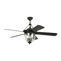
If you do NOT wish to use the light kit, align
grooves in metal cover with nodules inside LED
light kit. Push up on metal cover and then turn
metal cover to the RIGHT (clockwise) until it no
longer turns.
metal cover
motor
housing
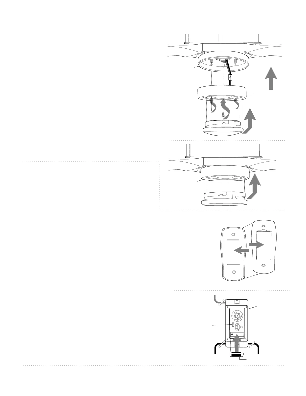
dimmer
switch
wall control
wire
wire
wire
12V battery
10. Handheld Remote Control
Assembly.
IN ORDER TO USE THE HANDHELD REMOTE CONTROL,
PLEASE CONTINUE WITH SECTION 10 for remote control
assembly instructions. If you have already installed the
wall control but do not wish to use the handheld
remote control, please proceed to Section 11.
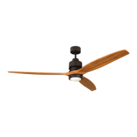
Gently pull on remote control cover to separate top and
bottom parts. [Refer to diagram 1.]
In order to use wall control as a handheld remote control, cut
each wire on wall control (that was not previously used)--use
wire cutters to cut off each wire as close to the wall control
as possible. [Refer to diagram 2.]
Install one 12-volt battery (included) in wall control. [Refer to
diagram 2.]
The dimmer switch (labeled ON and D) has been pre-set to
the "ON" position (ON). If you do not wish to have dimming
capability, please move the switch to the "OFF" position (D).
[Refer to diagram 2.]
Align holes in wall control with posts located on inside of TOP
part of remote control cover and press together firmly. Place
wall control into BOTTOM part of remote control cover,
aligning posts in top of remote control cover with post holes
in the bottom. [Refer to diagram 3 on the next page.]
[”Handheld Remote Control Assembly" continued on
next page.]
(top)
(bottom)
remote control
cover
diagram 1
diagram 2