Do you have a question about the Craftsman 139.53315SR and is the answer not in the manual?
Ensures door is balanced and serviced by professionals if not.
Crucial test for door reversal on obstruction.
Warnings about clothing, ropes, and entanglement.
Guidelines for visibility, children, and emergency use.
How to activate the opener using transmitters and wall buttons.
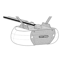
Steps for manual door release and operation.
Maintenance, limit, force, and chain tension adjustments.
Details on transmitter use and battery replacement.
Periodic checks for opener upkeep.
Describes the motor's automatic reset and opener light.
Covers safety system, limit adjustment, radio controls, and disconnect.
Explains how the trolley reconnects after manual release.
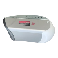
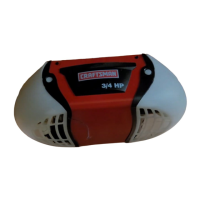
Details motor type, speed, and drive mechanism.
Lists safety features and control system details.
Provides the overall dimensions and weight of the opener.
Lists various transmitters, key switches, and code transmitters.
Includes infrared sensors and door clearance brackets.
Lists major parts found within the opener cartons.
Details the hardware required for assembly.
Details the hardware required for installation.
Lists common hand tools needed for installation.
Lists the electric drill and required drill bit sizes.
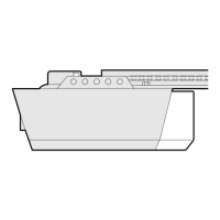
Step 1: Joining the three tee rail sections together.
Step 1: Securing the pulley bracket to the rail assembly.
Step 2: Installing the trolley onto the tee rail.
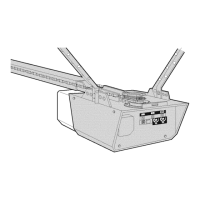
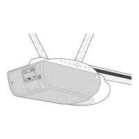
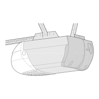
Step 3: Connecting the assembled tee rail to the opener chassis.
Explains the use of master links for chain and cable connections.
Step 4: Dispensing and connecting the chain and cable to the trolley and shaft.
Step 5: Adjusting chain tension for proper operation.
Confirms assembly completion and reiterates safety rules.
Step 1: Mounting the header bracket to the garage wall.
Header bracket placement for sectional doors with tracks.
Header bracket placement for one-piece doors without tracks.
Step 2: Connecting the tee rail assembly to the header bracket.
Step 3: Placing the chassis for sectional doors.
Step 3: Placing the chassis for one-piece doors.
Step 4: Mounting the opener chassis to structural supports.
Step 5: Installing the emergency release rope and handle.
Step 6: Selecting a safe location and mounting the push button.
Connecting optional accessories like sensors and key switches.
Step 7: Installing the light bulb and protective lens.
Step 8: Connecting the opener to a grounded power source.
Step 9: Attaching the bracket to sectional garage doors.
Step 9: Attaching the bracket to one-piece garage doors.
Step 10: Connecting the arm to the trolley for sectional doors.
Step 10: Connecting the arm to the trolley for one-piece doors.
Adjusting open and close travel limits for one-piece doors.
Step 1: Setting the door's open and close stopping points.
Step 2: Setting the force required to move the door.
Step 3: Verifying the door reverses on obstruction.
Optional step to install an infrared safety sensor.
Setting transmitter code switches to match the receiver.
Matching receiver codes to the transmitter for SR and non-SR models.
Solutions for when the opener doesn't respond to controls.
Addresses issues with short or unreliable transmitter range.
Solutions for doors not opening or closing fully.
Specific fixes for doors not closing completely.
Diagnosing and fixing random door reversals.
Troubleshooting light not turning on or off.
Addressing opener strain, high force needs, or motor hum.
How to operate the opener during a power outage.
Solutions for chain slack and noisy operation.
Identifies components within the rail assembly.
Lists parts used during the installation process.
| Brand | Craftsman |
|---|---|
| Model | 139.53315SR |
| Category | Garage Door Opener |
| Language | English |