CRAFTSMAN
The male spade terminals that are associated
with each-other face each-other broad-surface
to broad surface. See Figure 7.52.
Normally Closed
switch element:
Spades marked: "NC"
qormally Open
switch element:
Figure 7.52
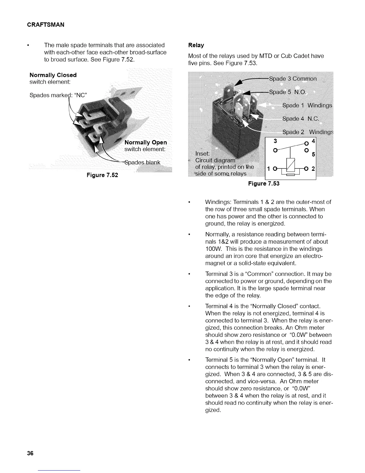
Relay
Most of the relays used by MTD or Cub Cadet have
five pins. See Figure 7.53.
Figure 7.53
Windings: Terminals 1 & 2 are the outer-most of
the row of three small spade terminals. When
one has power and the other is connected to
ground, the relay is energized.
Normally, a resistance reading between termi-
nals 1&2 will produce a measurement of about
100W. This is the resistance in the windings
around an iron core that energize an electro-
magnet or a solid-state equivalent.
Terminal 3 is a "Common" connection. It may be
connected to power or ground, depending on the
application. It is the large spade terminal near
the edge of the relay.
Terminal 4 is the "Normally Closed" contact.
When the relay is not energized, terminal 4 is
connected to terminal 3. When the relay is ener-
gized, this connection breaks. An Ohm meter
should show zero resistance or "0.0W" between
3 & 4 when the relay is at rest, and it should read
no continuity when the relay is energized.
Terminal 5 is the "Normally Open" terminal. It
connects to terminal 3 when the relay is ener-
gized. When 3 & 4 are connected, 3 & 5 are dis-
connected, and vice-versa. An Ohm meter
should show zero resistance, or "0.0W"
between 3 & 4 when the relay is at rest, and it
should read no continuity when the relay is ener-
gized.
36