ELECTRICALSYSTEM
To test a relay:
,
,
,
,
Test for continuity between the common and the
NC terminals using a DMM.
Test for continuity between the common and the
NO terminals using a DMM.
NOTE: There should be continuity with the NC
terminal and no continuity for the NO terminal. If
the results vary from this the relay is bad.
Apply 12 volts to terminals 1 and 2. This will
active the relay.
Test for continuity between the common and the
NC terminals.
,
Test for continuity between the common and the
NO terminals.
NOTE: There should be no continuity with the
NC terminal and continuity with the NO terminal.
If the results vary from this the relay is bad.
NOTE: To test the relay for burn contacts, do a
voltage drop test across the relay contacts while
the circuit is being used.
Diodes
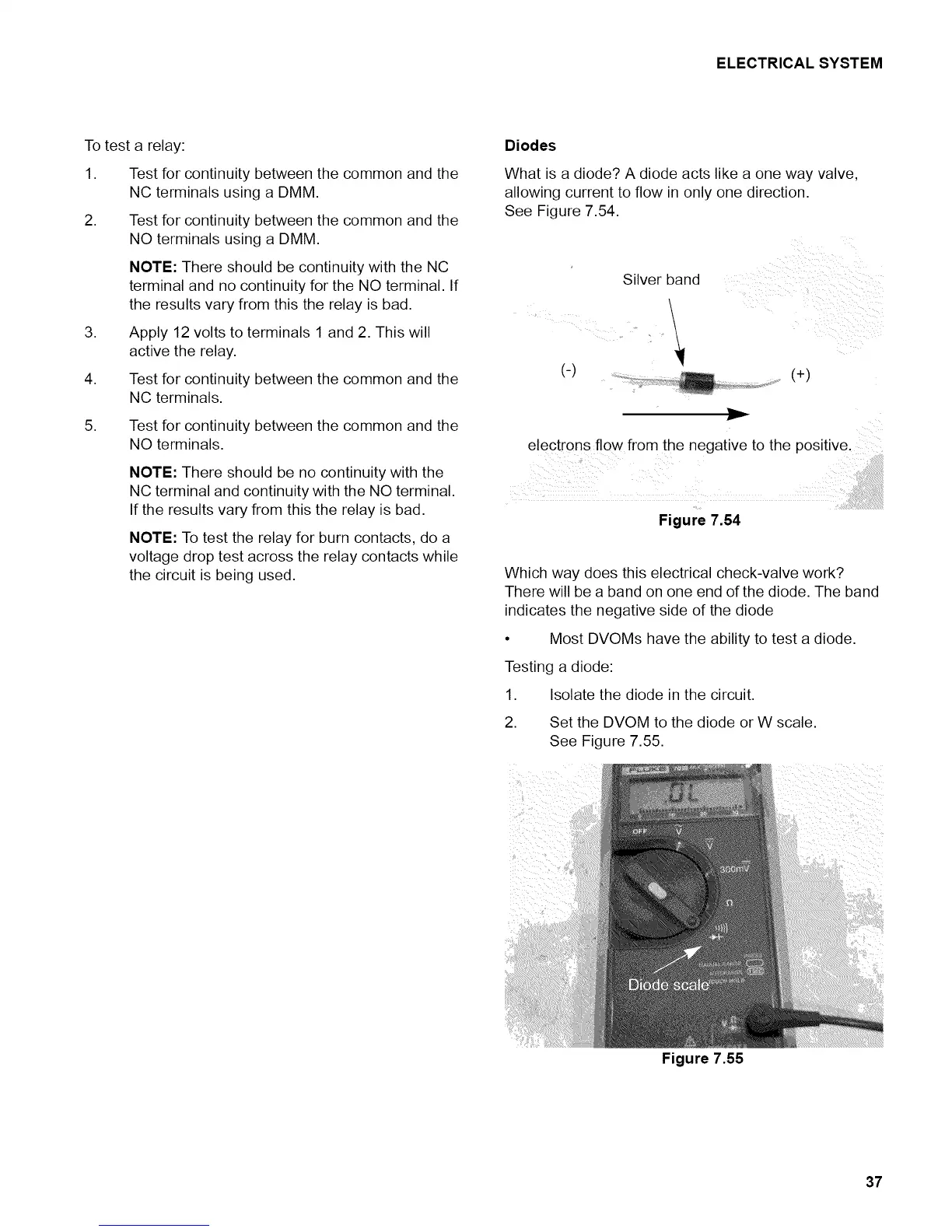
What is a diode? A diode acts like a one way valve,
allowing current to flow in only one direction.
See Figure 7.54.
(-)
Silver band
(+)
I1==.=
electrons flow from the negative to the positive.
Figure 7.54
Which way does this electrical check-valve work?
There will be a band on one end of the diode. The band
indicates the negative side of the diode
• Most DVOMs have the ability to test a diode.
Testing a diode:
1. Isolate the diode in the circuit.
2. Set the DVOM to the diode or W scale.
See Figure 7.55.
Figure 7.55
37