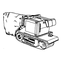
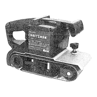
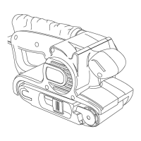
CRAFTSMAN 4 in. BELT SANDER -- MODEL NUMBER 315.117921
The model number will be found on a plate attached to the motor housing. Always mention the model number in all correspondence regarding your !
BELT SANDER or when ordedng repair parts.
I
PARTS LIST
Key Part
No. Number Description Quart.
1 970201-001 *
2 998367-001
3 607776-002
4 614658-010 *
5 989368-000
6 998366-203
7 706382-812
8 998411-004
9 726693-004 *
10 989366-000
11 976851-001
12 998372-001
13 616247-001
14 931744-059
15 999937-001
16 999448-003
17 998401-001 *
18 607461-001
19 998067-001
20 706239-820
21 622199-003
22 998374-004
23 998410-004
24 998390-005
25 967265-002
26 999927-002
27 622347-001
28 999923-001 *
Screw (#8-32 x 3/8 in. Pan Hd. T.F.) ............ 4
Belt Cover ..................................................... 1
Ddven Pulley ................................................. 1
Screw (#8-32 x 3/8 in. Pan. Hd.) .................. 3
Timing Belt .................................................... 1
Gear Housing Cover w/Beadng .................... 1
Washer ......................................................... 2
Pinion ............................................................ 1
Screw (#8-32 x 7/8 in. Fil. Hd.) ..................... 1
Pulley ............................................................ f
Data Plate ..................................................... 1
Tracking Screw ............................................. 1
Spdng ........................................................... 1
Washer ......................................................... 1
Blower ........................................................... 1
Wear Strip ..................................................... 1
Screw (#10-32 x 3/8 in. Wafer Hd.) .............. 1
Retaining Ring .............................................. 2
"S"Hook ....................................................... 1
Thrust Washer .............................................. 2
O Ring ........................................................... 2
Front Idler Roller w/Bearings ........................ 1
Idler Roller Shaft ........................................... 1
Yoke Assembly ............................................. 1
Pivot Pin ........................................................ 1
Release Lever Assembly .............................. 1
Washer. ..................................... :.................. 1
Screw (#10-32 x 1/2 in. Pan Hd.) ................. 1
Key Part
No. Number
29 998370-001
30 967262-001
31 998377-003
32 967878-003
33 612665-006
4 1-*
35 998379-001
36 998381-001
37 998391-001
38 703774-003
39 998388-001
40 976849-001
41 989592-001
42 999931-001
43 996393-O01
44 999347-001
45 989592-007
46 998398-001
47 998394-006
48 617966-030
49 998399-001
50 999507-001
51 998895-001
52 706239-825
53 622347-003
54 998413-001
55 616103-301
972000-492
Description Quan.
Bushing ......................................................... 2
Torsion Spdng .............................................. 1
Platen ....... ..................................................... 1
Glamor Plate ................................................. 1
* Screw (#10-32 x 7/8 in, Pan Hd. T.F.) .......... 2
Sanding Belt (4 in. x 21 in.) .......................... 1
Backing Pad .................................................. 1
Wear Plate .................................................... 1
Drive Roller Assembly .................................. 1
Steel Ball ....................................................... 1
Spacer Cup ................................................... 1
Logo Plate ..................................................... 1
* Screw (#8-10 x 1-1/8 in. Fil. Hd.) .................. 3
Blower Cover ................................................ 1
Shroud .......................................................... 1
Deflector ....................................................... 1
* Screw (#8-10 x 2-1/4 in. Fil. Hd.) .................. 2
Blower Housing ............................................. 1
Dust Bag ....................................................... 1
* Screw (#8-10 x 5/8 in. Pan Hd.) ................... 4
Handle Cover ................................................ 1
Cord .............................................................. 1
Switch ........................................................... 1
Washer ......................................................... 1
Washer ......................................................... 1
Gear .............................................................. 1
Thrust Washer .............................................. 1
Owner's Manual
NOTE: "A" - The assembly shown represents an important part of the Double Insulated System. To avoid the possibility of alteration or damage
to the System, service should be performed by your nearest Sears Repair Center. Contact your nearest Sears Retail Store for Service Center
information.
* Standard Hardware Item -- May Be Purchased Locally
*** Complete Assortment Available At Your Nearest Se__rsCatalog Order Or Retail Store
I .'lllJ I
17