2_
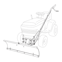
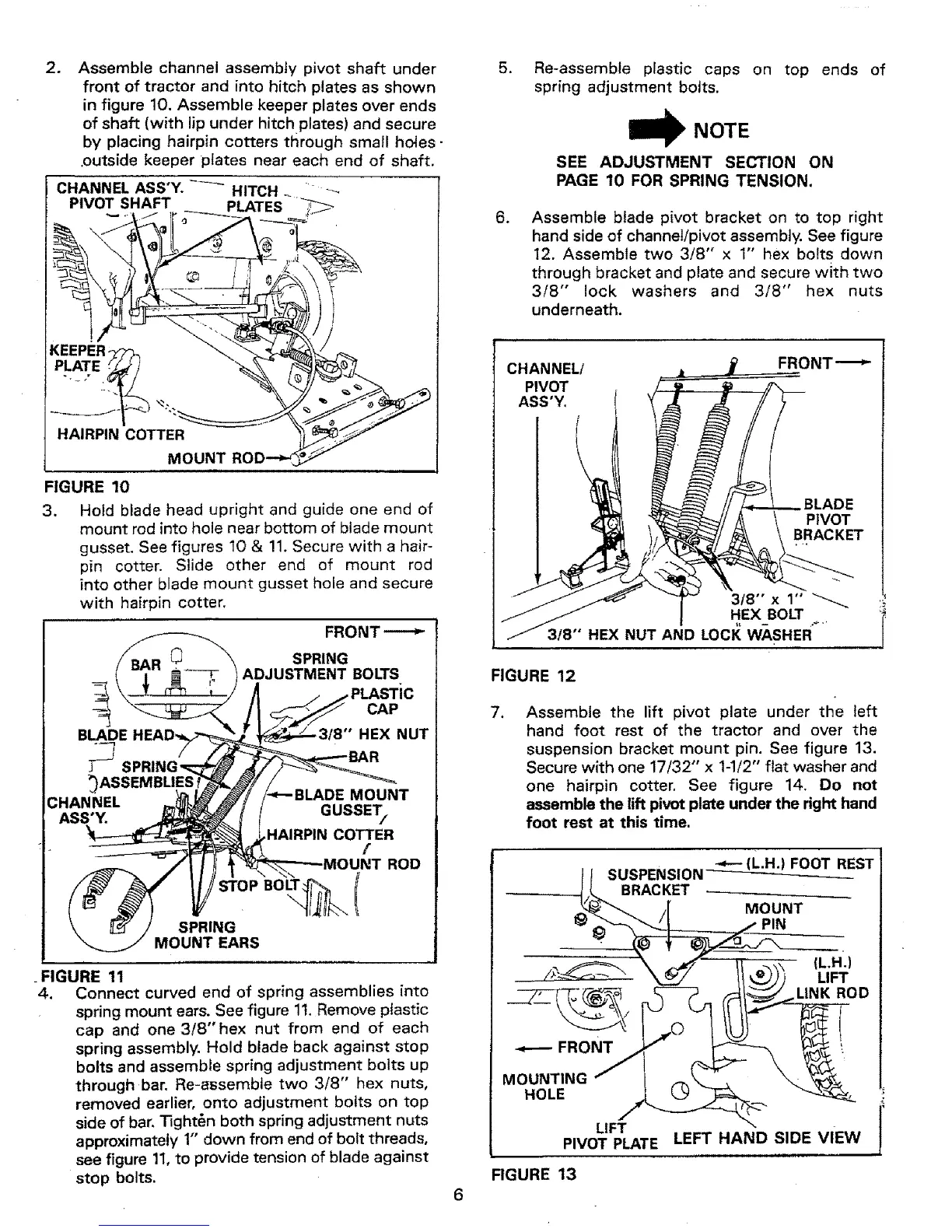
Assemble channel assembly pivot shaft under
front of tractor and into hitch plates as shown
in figure 10. Assemble keeper plates over ends
of shaft (with lip under hitch plates) and secure
by placing hairpin cotters through small holes-
.outside keeper plates near each end of shaft.
CHANNEL ASS'Y. -_-_ HITCH _ r
PIVOT SHAFT __ PLATES _ J
KEEPER
HAIRPIN COTTER
MOUNT
FIGURE 10
3. Hoid blade head upright and guide one end of
mount rod into hole near bottom of blade mount
gusset. See figures 10 & !1. Secure with a hair-
pin cotter. Slide other end of mount rod
into other blade mount gusset hole and secure
with hairpin cotter.
SPRING
ADJUSTMENT BOLTS
BLADE
CAP
HEX NUT
CHANNEL
ASS'Y.
MOUNT
GUSSET/
HAIRPIN COTTER
[
ROD
SPRING
MOUNT EARS
. FIGURE 11
4. Connect curved end of spring assemblies into
spring mount ears. See figure 1t. Remove plastic
cap and one 3/8"hex nut from end of each
spring assembly. Hold blade back against stop
bolts and assemble spring adjustment bolts up
through bar. Re-assemble two 3/8" hex nuts,
removed earlier, onto adjustment bolts on top
side of bar. "13ght6n both spring adjustment nuts
approximately 1" down from end of bolt threads,
see figure 11,to provide tension of blade against
stop bolts.
.
.
Re-assemble plastic caps on top ends of
spring adjustment bolts.
NOTE
SEE ADJUSTMENT SECTION ON
PAGE 10 FOR SPRING TENSION.
Assemble blade pivot bracket on to top right
hand side of channel!pivot assembly. See figure
12. Assemble two 3/8" x 1" hex bolts down
through bracket and plate and secure with two
3/8" lock washers and 3/8" hex nuts
underneath.
CHANNEL/
PIVOT
ASS'Y,
BLADE
PIVOT
BRACKET
318" x 1"
HEX BOLT
3/8" HEX NUT AND LOCI{ WASHER....
FIGURE 12
,
Assemble the lift pivot plate under the left
hand foot rest of the tractor and over the
suspension bracket mount pin. See figure 13.
Secure with one 17/32" x 1-1/2" flat washer and
one hairpin cotter. See figure 14. Do not
assemble the lift pivot plate under the right hand
foot rest at this time.
LIFT
PIVOT PLATE LEFT HAND SIDE VIEW
FIGURE 13