.
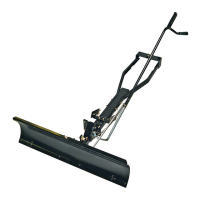
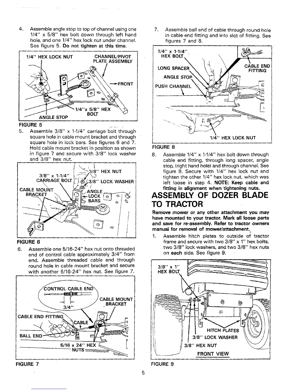
Assemble angle stop to top of channel using one
1/4" x 5/8" hex bolt down through left hand
hole, and one 1/4" hex lock nut under channel.
See figure 5. Do not tighten at this time.
114"' HEX LOCK NUT
CHANNEL!PIVOT
PLATE ASSEMBLY
I/4"x 5/8" HEX
BOLT
ANGLE STOP
FIGURE 5
5.
3/8" x 1-1t4"
CARRIAGE BOLT
\
CABLE MOUNT
BRACKET
Assemble 3/8" x 1-l/4" carriage bolt through
square hole in cable mount bracket and through
square hole in lock bars. See figures 6 and 7.
Hold cable mount bracket in position as shown
in figure 7 and secure with 3/8" lock wa'sher
and 3/8" hex nut.
,1
f8" HEX NUT
3tB" LOCK WASHER
FIGURE 6
6. Assemble one 5/16-24" hex nut onto threaded
end of control cable approximately 3/4"' from
end. Assemble threaded cable end through
round hole in cable mount bracket and secure
with another 5/16-24" hex nut. See figure 7.
MOUNT
•BRACKET
CABLE END
BALL EN[
FIGURE 7
7. Assemble ball end of cable through round hote
in cable end fitting and into slo,t of fitting. See
figures 7 and 8.
1/4" x I-1/4'"
HEX BOLT
CABLE END
LONG FITTING
ANGLE STOF
PUSH CHANNEL
1t4" HEX LOCK NUT
FIGURE 8
8. Assemble !/4" x 1-1/4" hex bolt down through
cable end fitting, through tong spacer, angle
stop, (right hand hole) and through channel. See
figure 8. Secure with 1/4" hex lock nut and
tighten the other !/4"' hex lock nut, which was
left loose in step 4. NOTE: Keep cable and
fitting in alignment when tightening nuts.
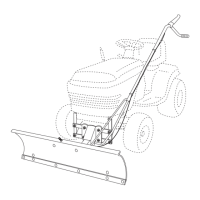
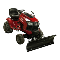
ASSEMBLY OF DOZER BLADE
TO TRACTOR
Remove mower or any other attachment you may
have mounted to your tractor. Mark all loose parts
and save for re-assembly, Refer to tractor owners
manual for removal of mower/attachment.
1. Assemble. hitch plates to outside of tractor
frame and secure with two 3/8" x 1" hex bolts,
two 3/8" lock washers, and two 3/8" hex nuts
on each side. See figure 9,
318°' x 1"'
HEX BOLT
J
FIGURE 9
5