ENGLISH
10
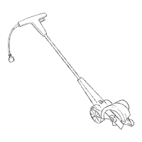
Pull-Up Edge Guide (Fig. I, J)
The edge guide is useful for cutting a straight path along
sidewalks. For landscaping or trenching in the yard the edge
guide can interfere with moving the edger through hard soil
or sod. The edge guide
18
can be adjusted so that the edger
will also perform trenching or landscapingoperations.
To Change Position of the Edge Guide
• To use without the edge guide, pull edge guide knob
17
away from the housing and slide the edge guide knob to
the upper guide notch
24
on the housing.
NOTE: In this position the edge guide is raised and the
blade can more easily trench or cut along the edges
of flower and shrubbery beds, and around trees in
preparation for trenching or sodremoval.
Cut Depth Adjustment (Fig.H)
WARNING: NEVER OPERATE
APPLIANCE WITHOUT GUARD FIRMLY IN PLACE.
The guard must always be properly attached on the
appliance to protect theuser.
WARNING: Do not use edger if the small
guard
21
does not move when adjusting depth. Ensure
the small guard is located toward the bottom of the
depth adjustment wheel
15
. Do not operate edger if
the small guard is not inplace.
The depth of cut can be adjusted to allow a deeper or
shallower cut, and to increase the life of the blade. There
are three adjustible settings that can be set using the depth
adjustment lever
16
.
1. Wait for blade to come to completestop.
2. Remove the batteryfrom thetool.
3. For a shallower cut, pull the depth adjustment lever away
from the housing and slide it down into one of the lower
depth adjustment slots
22
on thehousing.
4. For a deeper cut, pull the depth adjustment lever away
from the housing and slide it upwards into one of the
upper depth adjustment slots
23
on thehousing.
NOTE: Recommend 1.4" (3.5 cm) depth foredging.
5. Ensure the depth adjustment lever is fully seated in one
of the depth adjustment slots before using thetool.
NOTE: Thick overgrowth may drag on the guard. Reduce cut
depth to minimum to help reduce thiseffect.
Attaching the Auxiliary Handle (Fig. G)
For some models the auxiliary handle
4
may need to be
attached. If the model needs the auxiliary handle attached,
please refer to theseinstructions.
1. To attach the auxiliary handle, press in on the auxiliary
handle adjustment buttons
20
on both sides of the
upper housing.
Assembling the Handle Tubes (Fig.E, F, J)
CAUTION: NEVER use a sharp object to
move jacketed wires out of theway.
1. Remove knobs
8
and curved head bolts
19
from
handle tube mountingholes.
2. Remove tape which secures internal jacketed cable
totubes.
3. Slide middle tube
6
into lower tube
7
and fasten handle
tubes together with the knob and curved head bolt.
NOTE: When you first insert the bolt it may be necessary
to wiggle it carefully to get it past the jacketed cable
inside the tube.
4. There are two positions available for adjustment to
your preferred height setting. See Fig. I for upper
handle orientation.
NOTE: Ensure the cable moves smoothly into the handle
tubes whileassembling.
5. Push jacketed cable down into upper tube to remove
the slack. Slide the middle tube into the upper tube by
locating the groove and the bump.
6. Fasten upper tubes together with the remaining knob
and curved head bolt.
NOTE: When you first insert the bolt it may be necessary
to wiggle it carefully to get it past the jacketed wire
inside thetube.
ASSEMBLY AND ADJUSTMENTS
WARNING: To reduce the risk of serious
personal injury, turn unit off and remove the
battery pack before making any adjustments or
removing/installing attachments or accessories.
An accidental start‑up can causeinjury.
VersaTrack™
WARNING: Do not charge batteries while
charger is hung onTrackwall.
CRAFTSMAN chargers, except the CMCB101, can be
stored on CRAFTSMAN VersaTrack™ Trackwall. Hooks and
accessories are sold separately. Please refer to the VersaTrack™
Trackwall accessory sheet for furtherinformation.
NOTE: The CMCB101 charger is not CRAFTSMAN VersaTrack™
Trackwallcompatible.
SAVE THESE INSTRUCTIONS FOR
FUTURE USE
2. Position the auxiliary handle as shown in Figure G .
Partially push the auxiliary handle on so it will hold the
buttons in when you release them with your hand.
3. Push the auxiliary handle completely onto the housing
and position it slightly until it “snaps” intoplace.
NOTE: To adjust the auxiliary handle up or down, press in on
the buttons and raise or lower the handle.
NOTE: The handle should be adjusted so that your front arm
is straight when the edger is in the workingposition.