5
a ruler in both inches and metric units. The ruler measures the distance from
the inner edge surface of the blade, indicating the length of nished cut.
Push down on the leverage handle with one hand, keeping the other hand on
top of the material being cut. HAND PRESSURE should be used to power
the cutter, not foot pressure, body weight, other weight, or impact on the le-
verage handle. Keeping a hand on the material prevents it from moving and
ensures an accurate cut. Keep hands away from the blade, blade carrier, and
pressure rollers at all times, and keep hands out from under the material be-
ing cut. Stay alert and watch the cutting process at all times. (See Figure 6.)
Continue pushing the leverage handle until the material is cut, then raise it
with a hand on the grip and the assistance of the springs. Do not allow the
handle to rise rapidly and slam against the stop. Injury or damage may result.
After the cut, the material being cut may become stuck on the blade. Re-
move the stuck material from the blade using scrap material or other tool. Do
not use bare hands!
Prevent build-up of scrap, splinters and dust around the blade, blade carrier,
and on the cutting bed. Dust off using a piece of scrap or other tool.
Check the cut edges of any material that will be installed for splinters or sharp
edges. These may require removal by sanding or trimming to prevent injury.
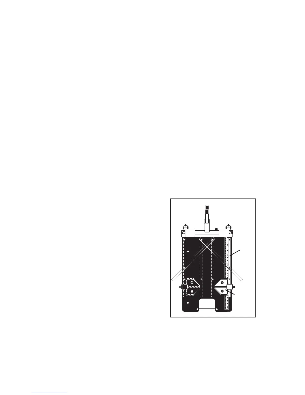
The fence of the cutter is movable to any
one of four straight positions, or one of two
45° angle positions (Figure 7). Moving the
fence helps position the material being cut
under different areas of the blade, so that
as areas of the blade become dull, other
areas that are still sharp can be more eas-
ily used. Cutting under different areas of
the blade also wears the sides of the cutter
mechanism more evenly over time, extend-
ing the life of the tool. Cutting mostly under
one side can wear out the cutter sooner.
To move the fence, remove the two wing
nuts from beneath the bed, and remove
the fence. Insert the fence into any pair of
holes as shown in Figure 7, then reattach
and tighten the wing nuts.
The cutter comes with a cut guide that attaches to the fence using a wing
screw (Figure 7). The cut guide can be used to set a length of cut for repeat-
ing a length of cut. If the fence is moved to the left or right, the cut guide can
be moved onto either side of the fence. The cut guide includes a 45° angle.
Figure 7
CUT
GUIDE
FENCE
 Loading...