5
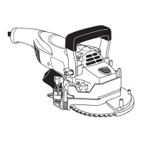
USING THE SAW:
Place the saw at on the oor near the wall to be under-
cut. Make certain the blade is set parallel to the oor.
Make sure the blade holding screw, and height locking
wing screws are tightened securely. Make sure the
ratchet teeth of the front handle interlock and the three-
arm knobs for the front handle are tightened securely
(Figure 11).
Always keep the front handle in the vertical position for
general undercutting.
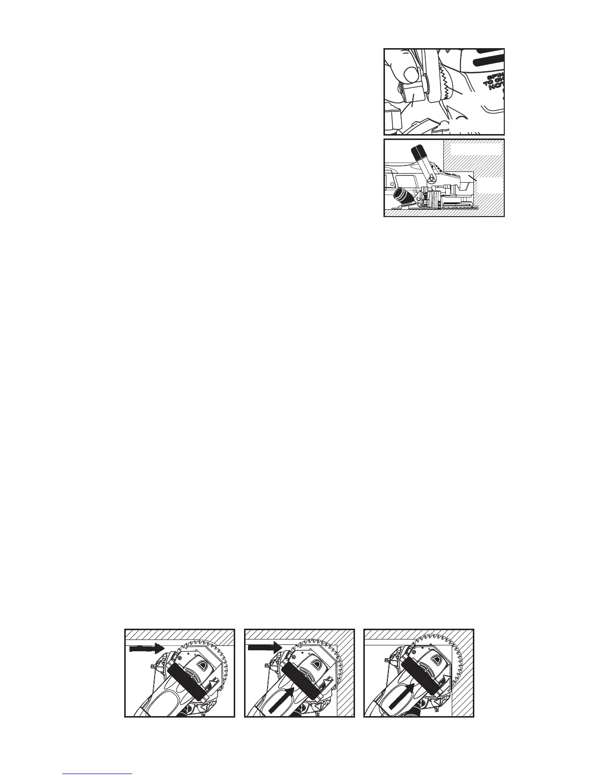
Lower the handle for undercutting toe spaces (Figure 12). Be sure to retighten
the front handle three-arm knobs.
Plug in the saw and grasp handles rmly with both hands. Keep one hand on the
front handle and one hand on the rear handle at all times.
Depress the safety lock button of the switch, then pull the switch trigger to start
the saw.
To start a cut, use the wall to push the blade guard back and expose blade. DO
NOT USE YOUR HAND!
First, plunge slowly to appropriate depth. Second, push the saw forward. Move
the saw from left to right only. Don't force the saw. Let blade cut at highest RPM
possible. Do not pull the saw towards you or run in reverse. Do not lift or angle
the saw, or saw kickback may result.
Remove the saw from the cut, and release the switch to stop.
INSIDE CORNER CUTTING:
When undercutting wood, cut towards the corner at 45˚ "left" angle (see Figure
13) until the depth gauge meets the right wall (see Figure 14). Otherwise, cut on
the 45º "right" angle with dust control (see Figure 10).
Stop and unplug saw. Fully retract depth gauge and continue the cut.
Push saw into the corner (see Figure 15).
WARNING: Depth gauge covers the blade and makes the saw safer to use. Always
unplug the saw and reset the depth gauge when inside corner cutting is complete.
Figure 11
RATCHET
TEETH
THREE-ARM
KNOB
Figure 12
TOE
SPACE
Figure 13
Figure 14
Figure 15