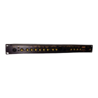
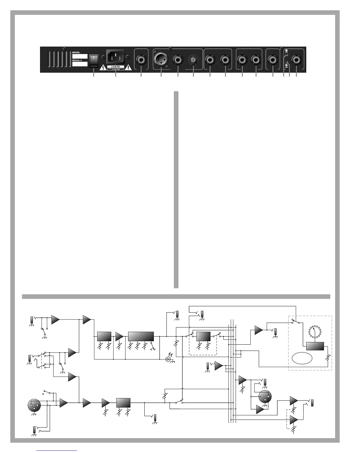
26: Power Switch. Turns the preamp on and off – lights up when the pre-
amp is on.
27: Line In. Connect the female end of the AC line cord here. Connect the
male plug to a suitable source of line voltage. Refer to the voltage
information on the back of the preamp for its voltage and current
requirements.
Note: This is a grounded plug. To avoid the possibility of electric
shock, DO NOT defeat the ground connection in any way!
28: Headphones/Line Out Master. Use this jack to connect a pair of stereo
headphones or to send an high impedance, unbalanced line level
stereo signal to a house sound board, a recording console or an exter-
nal power amplifier by means of an 1/4” stereo plug-terminated cable.
The level at this jack is controlled by the Master Level knob (#25, front
panel).
29: Low Z Bal. Use this jack to connect a low impedance, balanced line
level mono signal to a house sound board, a recording console or an
external power amplifier by means of an XLR-terminated cable. (Pin 1
is ground, pin 2 is signal +, and pin 3 is signal -.) The level at this jack
is controlled by the Line Out Level knob (#31).
30: High Z Bal. Use this jack to connect a high impedance, balanced line
level mono signal to a house sound board, a recording console or an
external power amplifier by means of an 1/4” stereo plug-terminated
cable. (Ring is signal +, tip is signal -, and sleeve is ground.) The level
at this jack is controlled by the Line Out Level knob (#31).
31: Line Out Level. Adjust the level of the line out signal with this control
- the further you turn to the right the stronger the signal. (This control
works independently from the master level control.)
32: Channel Two output. Use this jack to connect an unbalanced, line level
mono “direct out” signal from Channel Two to a house sound board, a
recording console or an external power amplifier by means of an 1/4”
mono plug-terminated cable. This signal is post-EQ and pre-Master
Level.
33: Channel One output. Use this jack to connect an unbalanced, line level
mono “direct out” signal from Channel One to a house sound board, a
recording console or an external power amplifier by means of an 1/4”
mono plug-terminated cable. This signal is post-EQ and pre-Master
Level.
34: Effects Loop Return. Patch into an external effects device using this
jack and the Effects Loop Send jack (#35). Connect a shielded cable
from the output jack of the external effects unit to this jack.
35: Effects Loop Send. Connect a shielded cable from this jack into the
input jack of the effects unit.
36: Footswitch - CA-1P: Connect a one-button footswitch (such as the
Crate CFP-1) here for remote on/off control of the chorus. When con-
nected, the footswitch overrides the front panel chorus on/off switch.
The footswitch tip controls the chorus; sleeve is ground.
CA-1PD: Connect a two-button footswitch (such as the Crate CFP-2)
here for remote on/off control of the DSP section and chorus. When
connected, the footswitch overrides the front panel chorus on/off
switch. The footswitch tip controls the chorus, ring controls the DSP;
sleeve is ground.
37: Channel Assignment switch. This switch assigns the tip and ring con-
nection of the Stereo Input jack (#39) as follows:
Switch OUT: Tip = Channel One, Ring = Channel Two
Switch IN: Tip = Channel Two, Ring = Channel One
38: Active/Piezo switch. Set this switch to match the type of pickup device
on your instrument: for active electronic pickups, set the switch to
“active” (out). For passive/magnetic pickups, set it to “piezo” (in).
39: Stereo Input jack. For instruments with stereo outputs (such as
acoustic guitars with pickups in the bridge and a built-in microphone),
connect a stereo 1/4” cable here to send one signal (for example, the
bridge pickups) to Channel One and the other to Channel Two. The
Channel Assignment switch (#37) determines which channel receives
which signal.
 Loading...