What to do if things go wrong
SELF HELP
If the shower is not working satisfactorily, make the following checks before calling out the contractor.
Any one of these adjustments could restore the performance.
a) The shower cycles
from HOT to COLD
The shower temperature is set too hot causing the thermal cut -out (safety device) to operate.
Turn knob “E” clockwise to increase water flow.
“MEDIUM” setting may need to be selected.
Slowly increase the water temperature by turning knob “E” anti-clockwise until a comfortable
showering temperature has been reached.
You MUST WAIT approx’ 20 seconds for each adjustment to affect the water temperature.
b) Water too HOT Increase water flow by adjusting the temperature control clockwise.
Clean showerhead holes. Select outer or combination spray pattern.
Switch power to “MEDIUM” setting. Increase pressure to water supply e.g. fully open service
valve or stop cock. Check hose is not kinked restricting the water flow.
c) Water too COLD Decrease water flow by adjusting the temperature control anti-clockwise.
Select inner or outer pattern only. Switch power to “HIGH” setting.
d) Spray pattern poor Clean showerhead and flush heater. Select outer/inner only.
e) Water goes cold
while using
shower
Check power setting lights are on.
Check water pressure has not fallen so far as to let pressure switch cut out,
e.g. Another tap drawing water off, indicated by “low pressure” light on.
Raise position of handset.
f) Broken parts Please contact our spares department on 0844 372 7750. Fitting instructions are provided
PROFESSIONAL SERVICE
If the above checks fail to restore the performance, you should seek professional help.
The person who installed the shower is probably the best one investigate and correct it, and is certainly the person to
contact if you have had a problem in the guarantee period.
The following additional checklist is provided for the benefit of the qualified service person.
WARNING: SWITCH OFF THE ELECTRICITY AT THE ISOLATOR BEFORE REMOVING THE COVER TO MAKE CHECKS
a) Water too HOT Water flow restricted by blockage in filter of solenoid valve. Switch off water, loosen inlet
connection to solenoid, remove filter in solenoid with long nosed pliers and flush clean.
b) Water too COLD Check circuit through thermal cut-out.
Check circuit through microswitches on the pressure switch.
Check each element circuit.
Check tightness of electrical connections.
c) Water discharges
from pressure
relief valve
Check for cause of high pressure and remove it.
Blockage on outlet e.g. blocked showerhead.
Replace the pressure relief disc (not covered by guarantee).
d) Water does not flow
when button “A”,
“B”or “C” is
pressed.
Check circuit through solenoid coil. If defective then replace.
Check circuit through microswitches. If defective then replace.
Possible PCB fault. If defective then replace.
Power supply not reaching shower.
Creda After Sales Service
We offer a technical advisory service on the telephone to contractors
and other customers with problems in the field.RING 0844 372 7766
Spare parts can be supplied against Credit or Debit cards. RING 0844 372 7750
Remember to quote the exact type of shower, as written on the front face.
The model and serial number are located on the bottom face of the shower.
Make a note of those numbers, and quote them if you call for advice.
Model No: 53-………………….. / Serial No:………………………
Note: You may be charged for a service call if you do not have a serial number.
How to maintain your Creda Shower
It is recommend that the shower unit, riser rail, hose etc. be cleaned using
a soft cloth and that the use of abrasive or solvent based cleaning fluid be
avoided, especially on any plated finishes.
We recommend that before any cleaning, the isolating switch be turned off,
thus avoiding accidentally switching on the shower.
The showerhead should be periodically cleaned as detailed on page 3.
YOU MUST REGULARLY INSPECT THE SHOWER HOSE FOR WEAR AND DAMAGE.
REPLACE IF NECESSARY, OR EVERY TWO YEARS, WITH OUR APPROVED PART.
5
Installation Instructions
ALL WIRING AND INSTALLATION MUST BE SUPERVISED BY A QUALIFIED ELECTRICIAN
WARNING: DO NOT INSTALL THIS SHOWER IN A ROOM WHERE IT MAY BE SUBJECT TO FREEZING.
We recommend that the installation is done in the following sequence.
a. Fixing the shower to the wall
b. Plumbing
c. Electrical connections
a. Fixing the shower to the wall
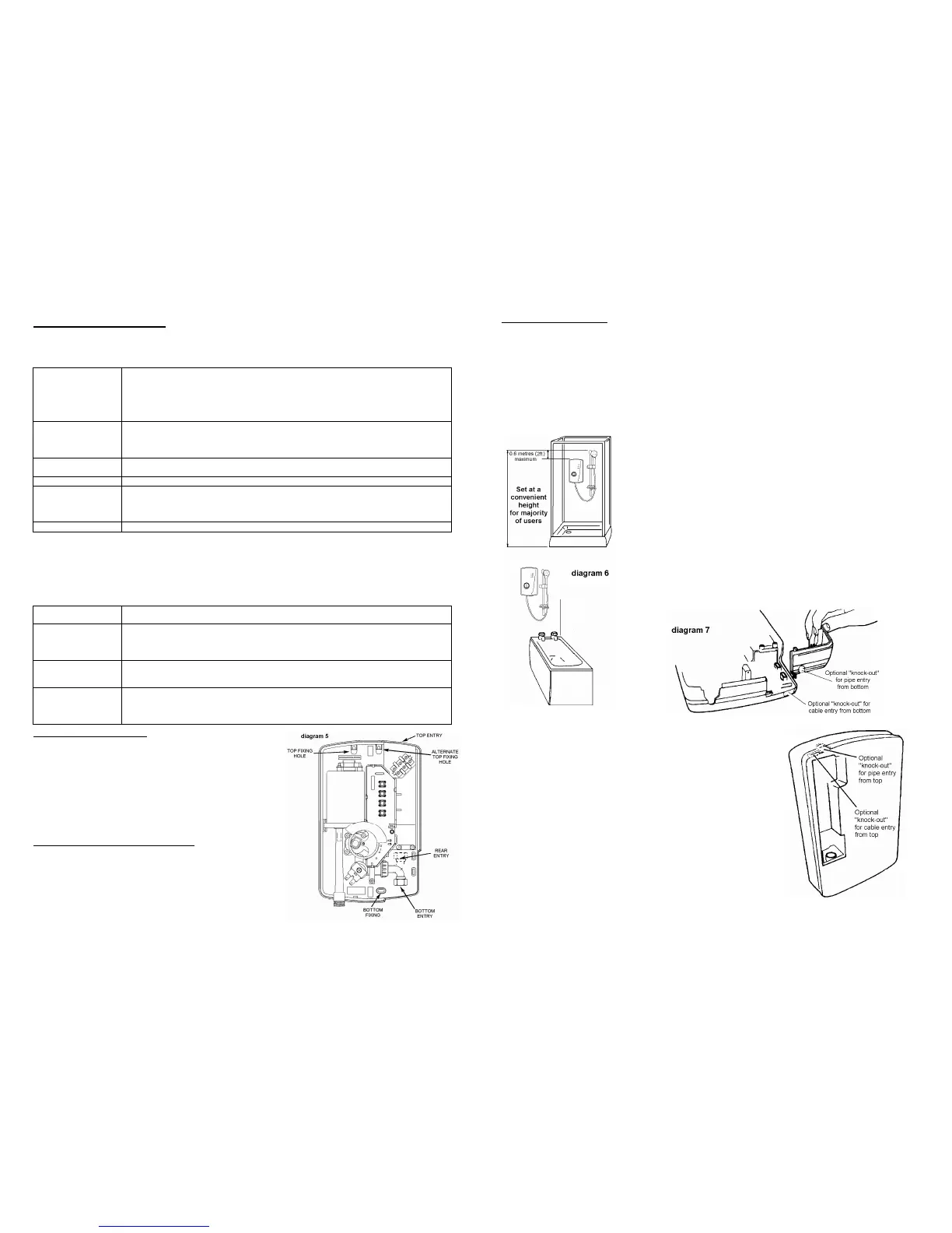
1. Position the riser rail at convenient height for majority of users as recommended in diagram 6 and mark its position
2. Position the heater so that the top of the unit is horizontal and level with,
or up to 0.6 metres (2ft) maximum below the top of the riser rail. Choose a
flat piece of wall to avoid the possibility of distorting the backplate thus making
the front cover a poor fit.
3. Adjust the position to get the most convenient arrangement taking the following
into account.
• The possible need to use the handset over the sink for hair washing etc.
• The heater must not be mounted in the direct spray from the handset.
• The handset must not be able to come into contact with used water in the
cubicle, bath or basin. If it can, even after the hose has been retained by the
soap dish (see diagram 11), then a vacuum breaker must be fitted. It should
be noted that these devices are liable to minor leakage so they must be
positioned so that any drips are not detrimental.
4. Fix the riser rail with screws provided. The fixing holes at the base of the
brackets will be disclosed by removing the plastic fronts. Assemble as shown in
diagram 11. Additional “knock-out” slots are available if required to improve
security.
5. Decide the position of the electrical cable to the unit. If top or bottom entry
is chosen (according to diagram 5), cut away the walls in the backplate as
shown in diagram 7.
6. Decide the position of entry of the cold water pipe into the unit.
If top, cut away the backplate.
If rear, please read the section on plumbing.
If bottom, remove the front cover (complete with knobs) and cut away the
detachable corner section as shown,
7. If you have not yet done so, remove the front cover (complete with knobs)
of the unit by undoing the retaining screws at the top and bottom of the
unit and lifting the cover off. Your shower is provided with 2 fixing
positions in the backplate (see diagram 5).
The top-fixing hole is a “key-hole” slot (another key-hole is provided for
alternate fixing), and should be marked and drilled first.
Tighten top screw with head protruding about 10mm from the wall and
hook the backplate over the screw head. This allows for correct and
accurate alignment of your shower before marking and fixing the bottom
position.
You may not wish to tighten up both screws at this stage as the holes are
elongated to allow for adjustment after other connections have taken place.
 Loading...