IF WATER IS TOO COLD
Turn knob “C” anti-clockwise to 11 o’clock
and continue turning anti-clockwise until you get
the water temperature of your liking.
Wait 20 seconds after each adjustment for the
water temperature to stabilise.
The final adjustment may be anywhere on the
dial.
If after turning fully anti-clockwise water is still
too cold, set shower pattern on shower handset to
outer or inner pattern only.
IF WATER IS TOO HOT
Turn knob “C” clockwise to 1 o’clock and
continue turning clockwise until you get the water
temperature of your liking.
Wait 20 seconds after each adjustment for the
water temperature to stabilise.
The final adjustment may be anywhere on the
dial.
If after turning fully clockwise, water is still too
hot, adjust knob “A” to “Med” (Medium) setting
and re-adjust as above.
Water flow will be reduced on this setting.
1. Ensure the electricity and water are turned on to the unit.
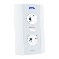
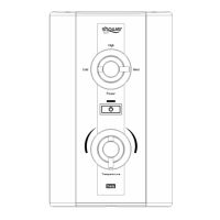
2. Your shower has 2 control knobs (see Diagram 6).
Knob “A” controls the 3 power settings.
The most popular is “High”.
There are also options for a “Med” (Medium)
or “Cold” shower (see notes 7 and 8).
Knob “C” controls the temperature of the water.
For this example turn knob “A” to “High”
and set knob “C” to “12 o’clock”, as shown in
Diagram 6. The “small bar” indicates knob setting.
3. Press button “B”.
The water will flow and the neon indicator will illuminate.
4. Allow about 20 seconds for the temperature of the water to stabilise.
It is recommended that you do not wholly enter the water spray during
this period, especially if the shower has just been used.
5. Once a temperature setting to your liking has been achieved, knob “C” will rarely need adjusting.
You must however take into account required adjustments for variations of incoming mains water
temperature between summer and winter (see “Effect of Seasonal Incoming Water Temperature
Changes” see page 14).
6. When you have finished showering, press button “B” only. You have no need to adjust knobs “A or C”.
The neon indicator will go out.
Switch off the electricity at the ceiling switch or local isolator.
7. The “Med” (Medium) setting of knob “A” reduces the power used by the shower giving a cooler shower or
the option of reduced water flow.
This option is mainly used for summer usage and if this is used then knob “C” must be re-adjusted.
8. The “Cold” setting of knob “A” will supply water without any heating.
9. Your shower is designed to stabilise temperature changes caused by water pressure fluctuations
(see “Effect of Other Water Devices on Incoming Water Supply” see page 14).
WARNING: DO NOT SWITCH THE SHOWER ON IF YOU SUSPECT IT OF BEING FROZEN.
WAIT UNTIL YOU ARE SURE IT HAS THAWED OUT.
WARNING: DO NOT OPERATE THE SHOWER IF WATER IS DISCHARGED FROM THE PRESSURE
RELIEF VALVE. MAINTENANCE IS REQUIRED BEFORE THE SHOWER CAN BE USED.
WARNING: CONSIDERATION SHOULD BE GIVEN TO SUPERVISING THE YOUNG, ELDERLY AND
THE INFIRM WHILST THEY USE THIS SHOWER.
HOW TO USE YOUR SHOWER SPA (DETAILED)
7
c) ELECTRICAL
WARNING: THIS SHOWER MUST BE EARTHED.
The electrical installation must be in accordance with the current BS.7671 (IEE Wiring Regulations)
and “Part P” of the Building Regulations and/or local regulations.
1. The shower unit is designed for a single phase AC electrical supply.
Please check the rating plate on the unit to see what details apply to your shower.
AS A GUIDE ONLY (* Only applies if external earth impedance is less than 0.35 Ohms)
Rating Cable Sizes
Cable Length
6.0mm²
10.0mm²
40A Type B MCB
27m Max.
8.5 / 7.8kW 240 / 230V
6.0mm²
10.0mm²
45A BS.1361 fuse
12m Max.*
21m Max.*
6.0mm²
10.0mm²
40A Type B MCB
27m Max.
9.5 / 8.7kW 240 / 230V
6.0mm²
10.0mm²
45A BS.1361 fuse
12m Max.*
21m Max.*
10.5 / 9.6kW 240 / 230V 10.0mm² 45A BS.1361 fuse 12m Max.*
Remember to upgrade the cable if it runs in thermal insulation in a loft, or for a longer distance.
2. A means for disconnection in all poles must be incorporated in the fixed wiring in accordance with
the wiring rules. We recommend a ceiling switch mounted in a convenient position.
3. If you have decided to connect the cable on the left hand side then please remove and use the
cable clamp that was provided along the right side (see Diagram 3).
WARNING: IF LEFT HAND SIDE CABLE ENTRY IS USED, THE MAINS CABLE OUTER SHEATH
MUST BE STRIPPED BACK TO THE LEVEL MARKED ON THE BACKPLATE, AND ALL
THREE CONDUCTORS MUST BE FULLY SLEEVED WITH THE SLEEVING PROVIDED
BETWEEN THERE AND THE TERMINAL BLOCK (SEE DIAGRAM 3a).
4. Connect cable to terminal block making sure that all the retaining screws are VERY TIGHT and that
no cable insulation is trapped under the screws.
WARNING: FAILURE TO COMPLY WITH THESE INSTRUCTIONS COULD RESULT IN FAILURE
OF THE TERMINAL BLOCK.
 Loading...