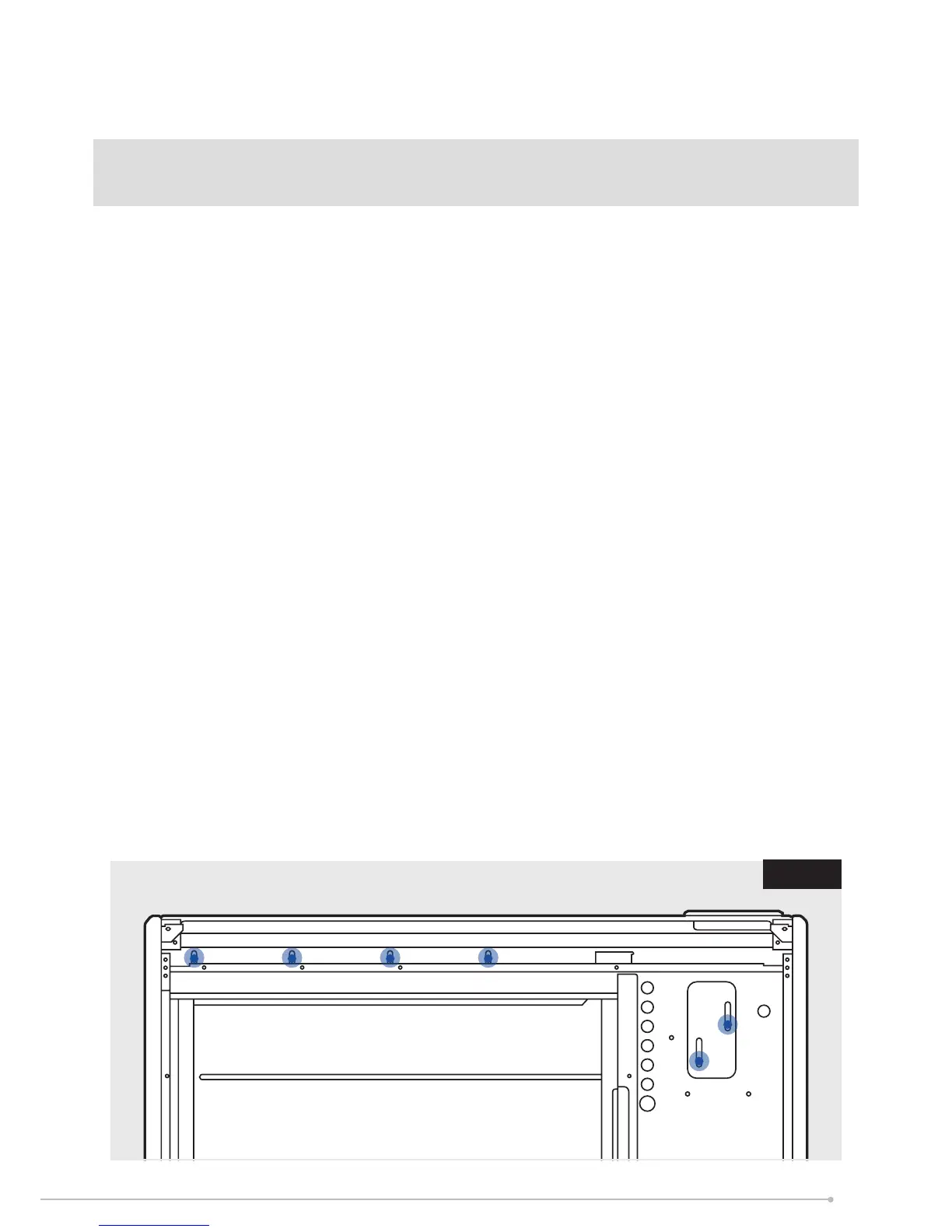
5. Place the heater in its nal position and mark the xing holes through the location holes
visible through the back of the heater.
6. Six xing positions must be selected for models TSRE100, TSRE125, TSRE150 and at least
4 xing positions for models TSRE050 and TSRE070. Fig. 6.
Common xing points for all heater sizes are shown in both Fig. 4 and Fig. 5.
Mark the positions for the xing holes towards the bottom of each slot. This allows the heater
to settle once the energy cells have been tted.
Move the heater away from the wall, drill the holes and t the wall xings best suited to the
application.
Secure the heater to the wall using correct quantity of screws required per model, using the
appropriate screw ttings.
NB: Do not fully tighten screws until energy cells are fully loaded to ensure full weight is
on feet and not on the wall xings.
NOTE: UNDER NO CIRCUMSTANCES SHOULD ANY SCREWS BE REMOVED WITHOUT
FIRST REMOVING ALL ENERGY CELLS FROM THE HEATER.
NEVER FREE THE HEATER FROM THE WALL WITH ENERGY CELLS REMAINING INSIDE
THE HEATER CAVITY.
NOTE: ANY FIXING DROPPED INTO HEATER MUST BE RETRIEVED AS THEY MAY
IMPACT PRODUCT SAFETY OPERATION.
Fig. 6
9