Do you have a question about the Crest Audio 8002 and is the answer not in the manual?
Explains terms, actions, warnings, indicators, and tips used in the manual.
Congratulates the user and introduces the Pro II Series amplifier's benefits.
Instructions for inspecting the amplifier after removing it from the shipping carton.
Guidelines for rack-mounting the amplifier, including front and rear support.
Explains the forced-air cooling system and ventilation requirements for optimal operation.
Details the voltage configurations for different regions and safe power-up procedures.
Outlines routine maintenance, primarily cleaning fan filters, and internal non-serviceability.
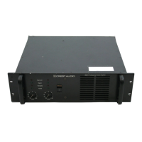
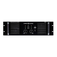
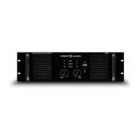
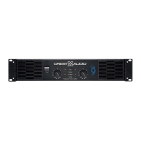
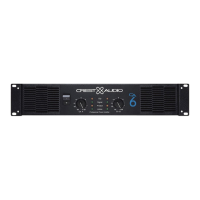
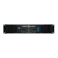
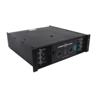
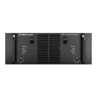
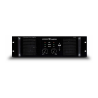
Details rack mounting ears, handles, fan outlets, LEDs, attenuators, and power switch.
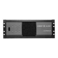
Covers rear panel connectors, mode selection, inputs, sensitivity, fan ports, and ground-lift switch.
Explains independent channel operation with separate controls and load impedance.
Describes amplifying a signal to both outputs using Channel A input and controls.
Details strapping channels for a powerful single-channel amplifier with specific wiring cautions.
Explains using male/female XLR connectors and input sensitivity options.
Covers speaker connections via binding posts and Speakon connectors for different modes.
Emphasizes proper installation, wiring, and operation of the amplifier.
Explains protection against DC voltage, subsonic frequencies, clipping, and thermal issues.
Details ACL, IGM, AutoRamp, Thermal, Short Circuit, DC Voltage, and Subsonic protection.
Guides on how to get service, contacting centers, distributors, or the factory.
Provides phone, fax, email, and mailing addresses for customer and technical support.
Lists detailed technical parameters like power, frequency response, impedance, and connectors.
Illustrates the signal path through preamp, attenuator, and output stage for channels A and B.
Provides tables showing wire gauge, load resistance, and power loss for various cable lengths in meters.
Provides tables showing wire gauge, load resistance, and power loss for various cable lengths in feet.
| Type | Power Amplifier |
|---|---|
| Number of Channels | 2 |
| Input Impedance | 10 kOhms Unbalanced, 20 kOhms Balanced |
| Frequency Response | 20 Hz - 20 kHz |
| Signal to Noise Ratio | 100 dB |
| Cooling | Variable speed fan |
| Dimensions | 19" x 3.5" |