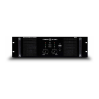
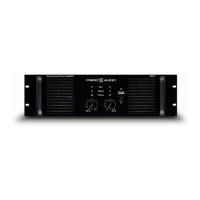
Do you have a question about the Crest Audio Pro Series 8002 and is the answer not in the manual?
Schematic diagram for the amplifier's display board.
Schematic of the display interface board including PFC storage functionality.
Schematic diagram for the amplifier's input PC board.
First page of the PRO2 Preamp schematic, detailing its circuitry.
Second page of the PRO2 Preamp schematic, continuing circuit details.
Schematic diagram for the amplifier's PFC power board.
Schematic diagram for the PFC control circuit.
Schematic diagram for the resonant converter control circuit.
Schematic diagram for the amplifier's suppression filter board.
Schematic diagram for the amplifier's output module PC board.
| Signal-to-Noise Ratio | > 100 dB |
|---|---|
| Damping Factor | > 200 |
| Input Impedance | 20 kOhms balanced, 10 kOhms unbalanced |
| Frequency Response | 20 Hz - 20 kHz |
| Total Harmonic Distortion | < 0.1% |
| Cooling | Variable speed fan |
| Connectors | XLR, 1/4" TRS |
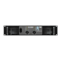
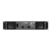
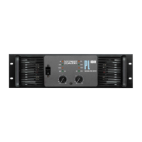
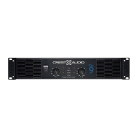
| Dimensions (H x W x D) | 3.5" x 19" |
| Input Sensitivity | 1.4V |
| Protection | Short circuit, thermal |
| Power Requirements | 120V, 60Hz |