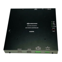
DMX512 Controller Crestron CGDMX-512BI
4
DMX512 Controller: CGDMX-512BI Operations & Installation Guide – DOC. 0003
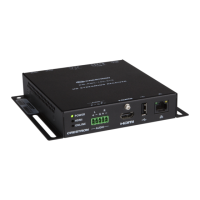
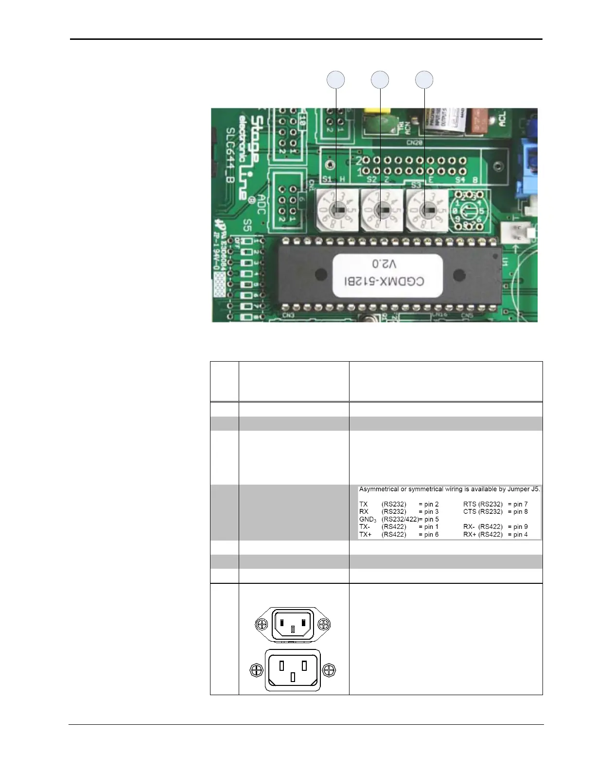
Connectors, Controls & Indicators
# CONNECTORS,
CONTROLS &
INDICATORS
DESCRIPTION
1 DMX512 Output [+Data(3), GND
2
(1), -Data(2)]
2 DMX512 Input [+Data(3), GND
1
(1), -Data(2)]
3 Status LED’s:
Power
CN COM
DMX512
Indicates that the device is powered.
Indicates traffic between the Crestron
processor and CGDMX-512BI.
Indicates a valid DMX512 input signal.
4 RS232/422 Interface-
connector to the
Crestron processor
S1 Rotary code switch Set Baud rate, factory 7
S2 Rotary code switch Set DMX512 speed, factory 1
S3 Rotary code switch Set interface mode, factory 1
100 – 240V ~2.4A 50/60
Hz
(1) IEC Socket, mates with removable power
cord (included)
 Loading...