Do you have a question about the Crestron MC4 and is the answer not in the manual?
Guidance on mounting the control system into a rack or onto a flat surface.
Lists the control system and additional items included in the product packaging.
Instructions for mounting the control system to a flat surface using mounting screws.
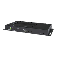
Details the front panel ports including PWR, HW-R, SW-R, ACQUIRE, and MEMORY slot.
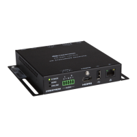
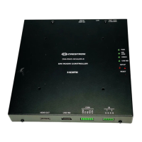
Details the rear panel ports including LAN PoE, CRESNET, EX/ER, IR, VER SI, IR IN, and USB.
Guidelines for placing the antenna for optimal signal strength and rack enclosure mounting.
Steps to access the web configuration interface using the control system's IP address.
Steps to access the web configuration interface using the Crestron XIO Cloud service.
Process for creating an administrator username and password for the web interface.
Steps to set the time zone on the control system via the web interface.
Instructions on setting the RF channel for optimal performance, including Wi-Fi band considerations.
Process for acquiring infiNET EX and ER devices to the control system's gateway.
QR codes and links to the product pages for MC4 and MC4-1.
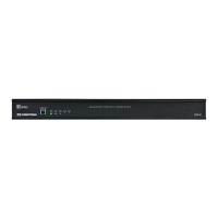
The Crestron MC4 and MC4-1 are 4-Series media room controllers designed to provide secure, high-performance, and cost-effective control processing and interfaces. Their compact size and flexible mounting options make them suitable for various applications, including single-room systems, small to medium-sized homes and offices, and multi-dwelling units (MDUs). These control systems feature a built-in infiNET EX® and ER wireless gateway, enabling them to acquire wireless devices, alongside numerous control ports for managing wired devices. The MC4 and MC4-1 are functionally similar, and for simplicity, this guide refers to both as "control system."
The control system offers versatile installation options, allowing it to be mounted in a rack or on a flat surface.
For rack mounting, the control system occupies 1U of rack space when utilizing the provided rack ears. To install, first attach the rack ears to the device. This involves inserting two threaded posts from the left rack ear upwards into the front opening of the left mounting flange of the control system, and repeating the process for the right rack ear. Four provided nuts are then used to secure the rack ears to the control system. Once the rack ears are attached, the control system can be secured to the rack rails using four rack mounting screws (not provided).
For surface mounting, the control system can be affixed to a flat surface such as a wall or under a table using four mounting screws (not provided). It can also be discreetly mounted behind a flat panel display or similar equipment.
The control system features various ports for connecting both wired and wireless devices.
The front panel includes indicators and buttons for PWR (Power), HW-R (Hardware Reset), SW-R (Software Reset), and ACQUIRE. There is also a MEMORY slot for an SD-compatible card, with contacts facing down.
The rear panel offers a comprehensive array of connection ports:
The control system is powered via PoE, either through a Crestron PoE injector (PWE-4803RU) or a Crestron PoE switch (CEN-SW-POE-5 or CEN-SWPOE-16), all sold separately. The included cables should not be extended. It is crucial to connect the chassis ground lug to a known earth ground circuit (such as building steel) to ensure proper grounding. Power should only be applied after all connections have been made.
The included dual-band 2.4/5.8 GHz antenna (2052945) must be placed in a location that optimizes signal strength and minimizes impedance. For detailed best practices, refer to the "Best Practices for Installation and Setup of Crestron RF Products" (Doc. 6689) available on www.crestron.com/manuals. If the control system is installed in a rack enclosure, the antenna should be mounted outside the enclosure using the Crestron ANT-EXT-10 (sold separately). Further information on this can be found in the "ANT-EXT-10 Installation Guide" (Doc. 7047) on www.crestron.com/manuals.
The control system can be configured using its web configuration interface, accessible via the control system's IP address or the Crestron XiO Cloud™ service.
The control system ships with DHCP enabled, requiring a DHCP server to access the web configuration interface via its IP address. To configure:
The Crestron XiO Cloud service allows for centralized management and configuration of supported Crestron devices across an enterprise. To use this service, a registered Crestron XiO Cloud account is required.
The first time the web configuration interface is accessed, a dialog box prompts the user to create an admin account. A similar message appears when connecting via Crestron Toolbox if an admin account hasn't been created.
The time zone must be correctly set on the control system to ensure accurate time settings are pushed to controlled devices.
The RF channel of the control system must be set prior to operation. The control system supports channels 11 through 26, with Crestron recommending channels 15 or 20. The default RF channel is 15.
For optimal performance in a Wi-Fi® network environment, avoid setting the RF channel within a Wi-Fi channel band.
Crestron RF devices fall into two categories: infiNET EX network devices and Crestron Extended Range (ER) devices. infiNET EX devices automatically match the gateway's channel, while ER devices require manual channel assignment to match the gateway's channel. Use Crestron Toolbox to set the control system RF channel by navigating to Functions > infiNET EX Gateway. Refer to the Crestron Toolbox help file for more information.
Crestron infiNET EX and ER devices communicate with the control system after being acquired by its internal gateway. A device can only be acquired to one gateway. Acquire mode is activated either from Crestron Toolbox or by pressing the ACQUIRE button on the control system's front panel.
| RAM | 2 GB |
|---|---|
| Ethernet Ports | 2 |
| Cresnet | Yes |
| Serial Ports | 4 |
| Digital Input Ports | 4 |
| Digital I/O Ports | 4 |
| USB Ports | 2 |
| HDMI Output | 1 |
| Mounting | Rack-mountable |
| Weight | 3.5 lbs |
| Internal Storage | 8 GB |
| Operating System | Linux |
| Relay Ports | 2 x Relay ports, normally open, isolated, rated 1 Amp, 30VDC |
| Power Supply | 24V DC |
| Audio Input | 1 |
| Audio Output | 1 |
| Control Ports | Cresnet, IR/Serial, Ethernet, Relays, Digital Inputs, USB, HDMI |