Professional Automation Mini Computer Crestron PAC2M
Connectors, Controls & Indicators (Continued)
#
CONNECTORS*,
CONTROLS &
INDICATORS
DESCRIPTION
10 PWR LEDs (A – B)
Indicates 24 Volts DC power present at the
respective segment (A and/or B).
11 NET LEDs (A – B)
Indicates communication with Cresnet
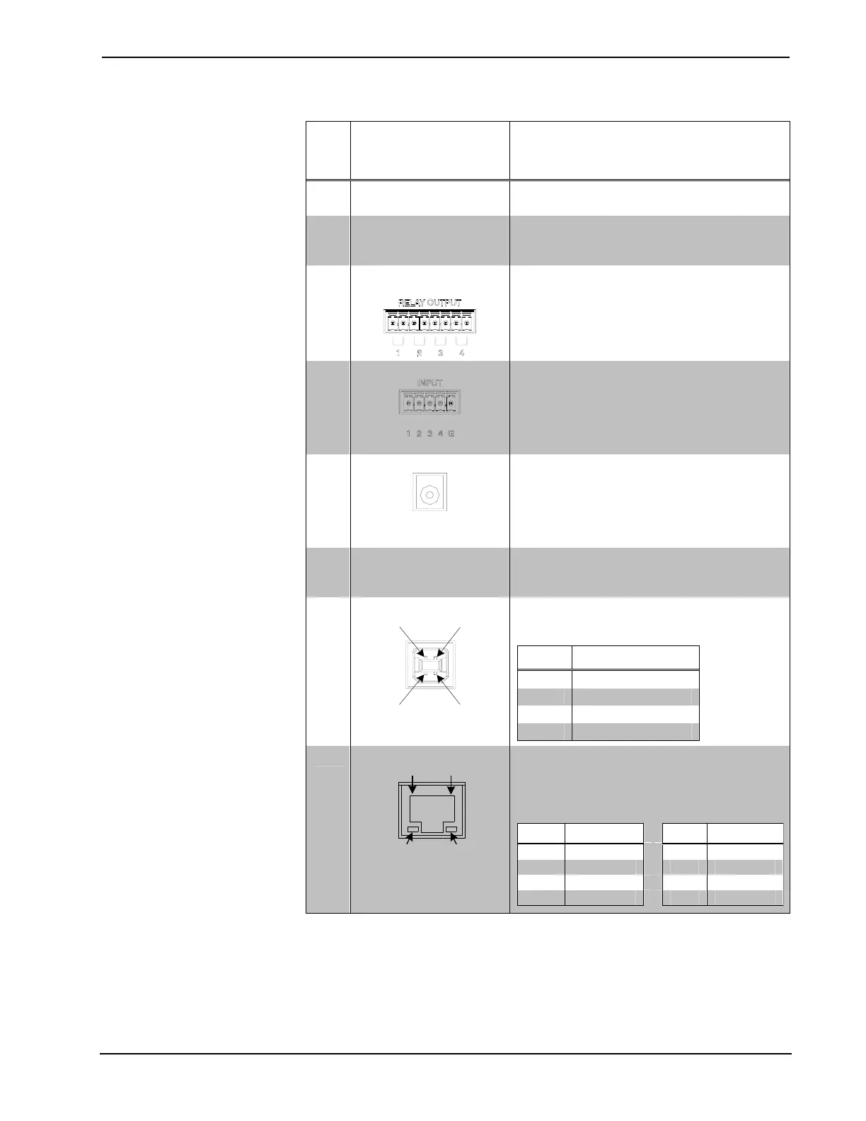
system by the respective segment (A and/or
B).
12
RELAY OUTPUT (1 –
4)
(1) 8-pin 3.5 mm detachable terminal block
comprising (4) normally open, isolated
relays;
Rated 1 Amp, 30 Volts AC/DC;
MOV arc suppression across contacts.
13
INPUT (1 – 4)
(1) 5-pin 3.5 mm detachable terminal block
comprising (4) digital inputs;
Rated for 0-24 Volts DC, referenced to GND;
Input impedance: 2.2 kΩ pulled up to 5 Volts
DC;
Logic threshold: 2.5 Volts DC nominal.
14
24 VDC
(1) 2 mm barrel DC power jack;
24 Volt DC power input, 2 amp maximum;
Paralleled with POWER input;
Powers processor and provides “internal”
power source to power modules and Cresnet
devices.
15 MEMORY
(1) MMC compatible card slot;
Accepts multimedia memory card (not
included) up to 1 GB.
16
COMPUTER
Pin 1 Pin 2
Pin 4 Pin 3
(1) USB Type B female USB 1.1 computer
console port (cable included).
PIN DESCRIPTION
1 +5 VDC
2 Data -
3 Data +
4 Ground
17
LAN
GREEN
LED
YELLOW
LED
PIN 8
PIN 1
(1) 8-wire RJ-45 with two LED indicators;
10BaseT/100BaseTX Ethernet port;
Green LED indicates link status;
Yellow LED indicates Ethernet activity.
PIN SIGNAL PIN SIGNAL
1 TX + 5 N/C
2 TX - 6 RC -
3 RC+ 7 N/C
4 N/C 8 N/C
* Interface connectors for G/INT/EXT, NET, LEFT, OVERRIDE, POWER, RELAY OUTPUT and
INPUT ports are provided with the unit.
8 • Professional Automation Mini Computer: PAC2M Operations Guide – DOC. 6507