3-Series Room Media Controller Crestron RMC3
Connectors, Controls, and Indicators
# CONNECTORS
1
,
CONTROLS, AND
INDICATORS
DESCRIPTION
1 PWR LED (1) Dual-color amber/green
LED;
Indicates operating power
supplied via PoE;
Amber indicates that device is
booting;
Green indicates that device is
operating
2 NET LED (1) Amber LED indicates
communication with Cresnet
system
3 MSG LED (1) Red LED, indicates that
processor has generated an
error message
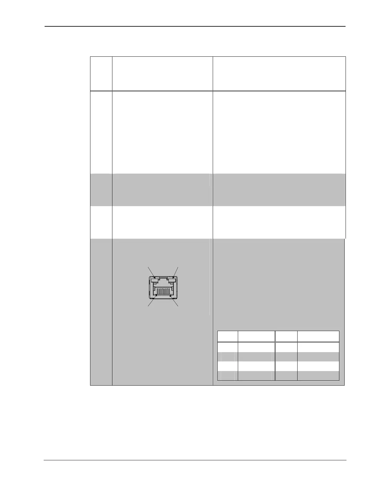
4 LAN PoE
2
Green
LED
Amber
LED
Pin 8 Pin 1
(1) 8-pin RJ-45 with 2 LED
indicators;
10BASE-T/100BASE-TX
Ethernet port, Power over
Ethernet compliant;
Green LED indicates
100BASE-TX link status;
Amber LED indicates Ethernet
activity
PIN SIGNAL PIN SIGNAL
1 TX + 5 N/C
2 TX - 6 RX -
3 RX + 7 N/C
4 N/C 8 N/C
(Continued on following page)
12 Room Media Controller: RMC3 Operations & Installation Guide – DOC. 7558B