Crestron RMC3 3-Series Room Media Controller
Connectors, Controls, and Indicators (Continued)
# CONNECTORS
1
,
CONTROLS, AND
INDICATORS
DESCRIPTION
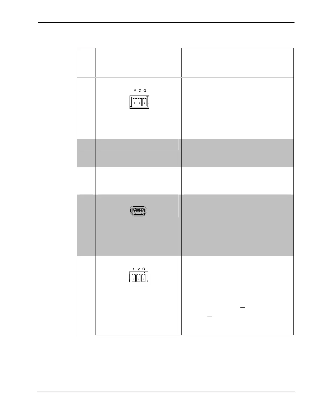
5 NET
(1) 3-pin 3.5 mm detachable
terminal block;
Cresnet master port (data only,
no power
3
)
Y: Data
Z: Data
G: Ground
6 HW-R Button (1) Recessed miniature push
button for hardware reset
(reboots the processor)
7 SW-R Button (1) Recessed miniature push
button for software reset
(restarts the SIMPL program)
8 USB-OTG
(1) USB Type Mini-AB female,
USB OTG port for computer
console and USB mass
storage devices (6 ft A male to
Mini-B male cable and A
female to Mini-A male adapter,
included)
9 DIGITAL IN 1-2
(1) 3-pin 3.5 mm detachable
terminal block comprising (2)
digital inputs (referenced to
GND);
Input voltage range: 0-24 Vdc;
Logic threshold: >
2.0 Vdc
0/low, <
1.1 Vdc 1/high
Input impedance: 2.2 kΩ pulled
up to 5 V
(Continued on following page)
Operations
& Installation Guide – DOC. 7558B Room Media Controller: RMC3 13