3-Series Room Media Controller Crestron RMC3
Connectors, Controls, and Indicators (Continued)
# CONNECTORS
1
,
CONTROLS, AND
INDICATORS
DESCRIPTION
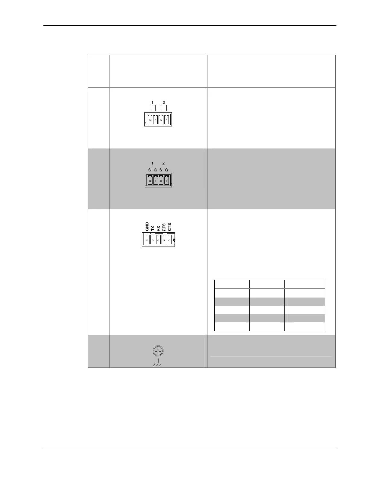
10 RELAY 1-2
(1) 4-pin 3.5 mm detachable
terminal block comprising (2)
normally open, isolated relays;
Rated 1 A, 30 Vac/Vdc;
MOV arc suppression across
contacts
11 IR 1-2
(1) 4-pin 3.5 mm detachable
terminal block comprising (2)
IR/Serial output ports;
IR output up to 1.2 MHz;
1-way serial TTL/RS-232
(0-5 V) up to 115.2 kBd
12 COM
(1) 5-pin 3.5 mm detachable
terminal block;
Bidirectional RS-232/422/485
port;
Up to 115.2 kBd;
Hardware and software
handshaking support
RS-232 RS-422 RS-485
GND GND GND*
TX TX- TX-/RX-
RX RX+ Not Used
RTS TX+ TX+/RX+
CTS RX- Not Used
13 G
(1) 4-40 screw, chassis ground
lug
1. Interface connectors for NET, DIGITAL IN 1-2, RELAY 1-2, IR 1-2, and
COM ports are provided with the unit.
2. The pinout table indicates signal connections. Power (dc) applied by Ethernet
power sourcing equipment (PSE) can connect to signal pins or N/C pins.
3. The NET (Cresnet) port on the RMC3 is a 3-pin connector that provides
connectivity for Cresnet data only—the port does not provide power. The Cresnet
power conductor does not terminate to the RMC3. An external Cresnet power
supply is required to provide power for Cresnet devices.
14 Room Media Controller: RMC3 Operations & Installation Guide – DOC. 7558B