quickstart guide
TST-600
www.crestron.com
888.273.7876 201.767.3400
Specifications subject to
change without notice.
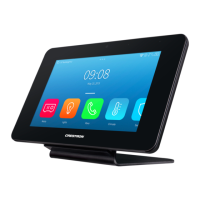
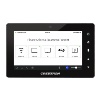
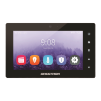
TST-600
5.7” Wireless Touch Screen
5
Establish Communication
QUICKSTART DOC. 7381E (2034457, Sheet 2 of 2) 09.14
3
Use Crestron Toolbox™ for communicating with the TST-600; refer to the Crestron Toolbox help file for details. There are three methods of communication:
TCP/IP, Indirect (using Wi-Fi) and USB.
When using a wired LAN, the TST-600 must be placed on the TST-600-DS Docking Station, which must be connected to a powered TST-600-IMCW
Interface Module (both included) or it must be placed in the TST-600-DSW Wall Mount Docking Station (sold separately). It must also be in LAN mode.
Refer to section ➍ “Networking Setup” on page 2 for details.
For regulatory compliance information, refer to Doc. 7382.
Ethernet Communication (LAN Communication is Enabled)
Wi-Fi Communication (Wi-Fi Communication is Enabled)
USB Communication
Using Wi-Fi, the TST-600 can communicate directly with the PC via the network.
6
Hardware Hookup
When the TST-600 is set for Wi-Fi, after it has been successfully acquired by a CEN(I)-ERFGW-POE gateway (refer to
section
➌
), the TST-600 does not require any physical connections for wireless operation.
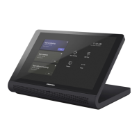
When set for wired LAN , the TST-600 must be placed on the TST-600-DS Docking Station, which must be connected
to a powered TST-600-IMCW Interface Module (both included) or it must be placed in the TST-600-DSW Wall Mount
Docking Station (sold separately).
For details, refer to the TST-600-DS Installation Guide (Doc. 7433) and the TST-600-IMCW Installation Guide (Doc.
7385) at www.crestron.com/manuals.
LAN:
10BASE-T /
100BASE-TX
Ethernet to LAN
24 G:
24 VDC
Power Input
TO PANEL:
Connect to
TST-600-DS
Docking Station via
10-Pin RJ-50 Cable
(Provided with
Docking Station)
PWR*:
From DC
Power Pack
TST-600-IMCW (Front and Rear Views)
7
Dimensions
1.59 in
(41 mm)
1.07 in
(28 mm)
TST-600 (Front and Side Views)
* A ferrule dust cap is provided to cover the dc power jack when not in use.
8.08 in
(206 mm)
5.60 in
(143 mm)
4.51 in
(115 mm)
3.38 in
(86 mm)
5.10 in
(130 mm)
TST-600 connects to PC via Ethernet:
1. Use the Device Discovery Tool (click the icon) in Crestron Toolbox to detect all Ethernet devices on the network and their IP configuration.
The tool is available in Toolbox version 1.15.143 or later.
2. Click on the TST-600 to display information about the device.
The USB port on the TST-600 connects to USB port on the PC via the included Type A to Type B USB cable:
1. Select Tools > System Info.
2. Click the icon.
3. For Connection Type, select USB. When multiple USB devices are connected, identify the TST-600 by entering “TST-600” in the Model text box,
the unit’s serial number in the Serial text box or the unit’s hostname (if known) in the Hostname text box.
4. Click OK. Communications are confirmed when the device information is displayed.
TST-600
PC Running
Crestron Toolbox
LAN
PC Running
Crestron Toolbox
CEN-WAP-ABG
NETWORK
PoE
LAN
TST-600
LAN
PC Running
Crestron Toolbox
USB
TST-600
 Loading...