EasyManua.ls Logo

Crestron USB-EXT - User Manual

Crestron USB-EXT
2 pages
Print Icon
To Next Page IconTo Next Page
Loading...
quickstart guide
USB-EXT
www.crestron.com
888.CRESTRON
Specifications subject to
change without notice.
QUICKSTART DOC. 7204B (2031178) 10.16
1
USB-EXT
USB over Twisted Pair Extender
1
The Crestron
®
USB over Twisted Pair Extender (USB-EXT) delivers
USB signal extension for use in various commercial and residential
applications. The USB-EXT enables wire runs up to roughly 300 ft
(100 m) over a single twisted-pair cable without requiring any
specialized installation.
The USB-EXT is compatible with USB 1.1 and High-Speed USB 2.0,
and it supports almost any USB device, including keyboards and
mice, game controllers, cameras, mobile devices, printers, switches,
and memory devices. Additionally, it is compatible with Windows
®
and
macOS
software without needing to install any additional drivers.
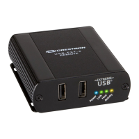
The USB-EXT is composed of two extender components. The “local”
extender connects to a computer or other USB host, while the
“remote” extender provides connections for USB devices at some
remote location. Linking the two extender components requires only
one run of CAT5 (or better) twisted-pair cable.
The USB-EXT contains a local extender, a remote extender, a power
supply, and a USB cable.
Introduction
NOTE: Crestron does not guarantee that the USB-EXT is compatible
with all USB devices.
CAUTION: The ambient operating temperature is 32º to 122 ºF
(0º to 50 ºC). The extenders may be hot to the touch when operating
at or near the high end of this temperature range.
!
On the local and the remote units, check that the Power, Host, and Link LEDs are on and that the Activity LED for the connected USB
port is blinking. If any LED does not light, then the cabling between the local and remote units is not properly installed or is defective.
Verify that the device is properly installed on the computer.
For Windows:
Open Device Manager, and then expand the entry for Universal Serial Bus controllers. If the USB-EXT has been properly installed, it
is listed as a “Generic USB Hub.”
For macOS:
Open System Profiler. In the left-hand column under Hardware, select USB, and then inspect the right-hand panel. If the USB-EXT
has been properly installed, it is listed as a “Hub” under the USB High-Speed Bus/USB Bus.
If the unit is not detected correctly or fails to detect, consult the Troubleshooting section on the following page.
5
Checking the Installation
For Regulatory Compliance information,
refer to the latest version of Doc. 7205.
201.767.3400
1. Install any software on the computer that is required to operate the USB device(s). Refer to the documentation for the USB
device(s) for installation instructions.
2. Connect the USB device to either USB port on the front of the remote extender.
3. Check that the device is installed and that it is detected properly by the operating system.
4
Connecting a USB Device
Remote extender (front)
Remote extender (rear)
Local extender (front)
Local extender (rear)
To USB hub or
USB HID devices
From
power pack
To computer
or USB hub
CAT5 cable
After determining where the local computer and the remote USB
device(s) are to be located, place the local and remote boxes of the
USB-EXT on a flat surface near each of the two locations. The rubber
feet help ensure that the units do not shift.
2
Mounting
1. Insert one end of the supplied USB cable into the local extender
and the other end into a USB Type A port on the computer.
2. Using CAT5 (or better) cable, connect the Link ports of the local
and remote extenders. Do not connect the Link ports to an Ethernet
LAN or to any other network device.
3. Plug the power adapter into the local extender, and then plug the
24 V power adapter into an AC outlet.
3
Installing
NOTE: If using preinstalled in-wall CAT5 wiring, plug one end
of the CAT5 patch cable (not supplied) into the Link port on the
local extender, and plug the other end of the patch cord into the
wall outlet near the host computer. Plug one end of the second
CAT5 patch cord (not supplied) into the Link port on the remote
extender, and plug the other end of the second patch cable into
the wall outlet near the USB device. Ensure that the two patch
cables and the in-wall cabling do not exceed ~330 ft (100 m).


Questions and Answers

  • A
    Angel JacksonAug 14, 2025
    What to do if Host LEDs on Crestron USB-EXT are blinking?
    • B
      Brandon WilliamsAug 14, 2025
      If the Host LEDs on your Crestron Extender are blinking, it could be due to the remote unit being in suspend mode because the computer is in a suspend/standby state. Try resuming the operating system. Another cause might be that no USB devices are attached; in this case, attach a USB device to the USB-EXT.
  • M
    Mrs. Connie Williams DVMAug 17, 2025
    What to do if all LEDs are on but USB device doesn't operate correctly on Crestron USB-EXT?
    • K
      Kimberly SchmidtAug 17, 2025
      If all LEDs are illuminated but your USB device isn't working correctly or is detected as an 'Unknown Device', this indicates the USB device may be malfunctioning. Try disconnecting the Crestron Extender and connecting the USB device directly to the computer. If it still doesn't work, consult the device's documentation. If it works when connected directly, try connecting a different device to the Extender. If the second device works, the first one may be incompatible. Consider updating the system BIOS, chipset, or USB host controller drivers.
  • S
    Sarah MackAug 21, 2025
    How to fix no LEDs on remote Crestron Extender?
    • C
      christyholtAug 21, 2025
      If no LEDs are lit on the remote Crestron Extender, the issue is likely that it isn't receiving power over the CAT5 cable. Ensure the CAT5 cabling between the local and remote extender is properly installed. Verify the power pack connection to the local extender and check that both the local and remote extender's Power LEDs are illuminated.
  • A
    Anna StephensAug 25, 2025
    What to do if Link LEDs are off on Crestron USB-EXT Extender?
    • K
      Kevin KhanAug 25, 2025
      If the Link LEDs are off on both the local and remote Crestron Extender, there's likely no connection between them. Ensure that the CAT5 cable is correctly connected between the local and remote extenders, and that you're using CAT5 cable (or better), UTP with a straight-through connector, no crossovers, and eight RJ-45 connectors at both ends.
  • M
    Michele FritzAug 27, 2025
    Why is USB LED orange on Crestron USB-EXT Extender?
    • J
      James CurryAug 27, 2025
      If the USB LED on the remote Crestron Extender is orange and the device isn't functioning, it indicates an overcurrent condition. This happens when the USB device draws more power than the specified 500 mA. To resolve this, cycle the power of the local extender.
  • R
    Rebecca AvilaAug 30, 2025
    What to do if Link LEDs are on but Host LED is off on Crestron Extender?
    • T
      Tanya SteeleAug 30, 2025
      If the Link LEDs are on but the Host LED is off on your Crestron Extender, the host computer may not be powered on, so power on the host computer. Another possibility is that the local extender isn't properly connected to the computer; check the connection. Also, the computer may not support USB hubs; connect the USB-EXT to a computer that supports USB hubs. Finally, the USB-EXT may be malfunctioning. In this case: 1. Disconnect power to the local extender. 2. Disconnect all USB devices from the remote extender. 3. Disconnect the local extender from the computer. 4. Reconnect the local extender to the computer. 5. Reapply power to the local extender. 6. If using Windows, ensure the device is recognized as a 'Generic USB Hub' in Device Manager.
  • G
    gerald50Sep 2, 2025
    How to fix no LEDs on local Crestron Extender?
    • S
      Samantha DelgadoSep 2, 2025
      If no LEDs are illuminating on the local Crestron extender, the most likely cause is that it's not receiving power from the AC power adapter. Ensure that the AC power adapter is properly connected to the local extender and that the AC adapter is connected to a live power source.
  • G
    Gregory WhiteSep 6, 2025
    Why do Host and Link LEDs blink intermittently on Crestron USB-EXT?
    • B
      blakeangelaSep 6, 2025
      If the Host and Link LEDs on both the local and remote Crestron Extender are blinking intermittently, it indicates a firmware mismatch between the local and remote extenders. Use a different local/remote pair that have the same firmware version.
  • A
    Autumn MooreSep 9, 2025
    What causes loss of functionality due to electrostatic discharge on Crestron USB-EXT Extender?
    • S
      Scott BellSep 10, 2025
      If you're experiencing a loss of functionality due to electrostatic discharge with your Crestron Extender, the unit might be improperly grounded. Check that all ground connections have been properly made.

Summary

Introduction

Mounting

Installing

Connect USB Cable

Connect the supplied USB cable to the local extender and computer's USB Type A port.

Connect CAT5 Cable

Link local and remote extenders using CAT5 cable, avoiding network connections.

Connect Power Adapter

Plug the power adapter into the local extender and then into an AC outlet.

In-Wall CAT5 Wiring

Notes on using preinstalled in-wall CAT5 wiring for the USB-EXT connection.

Connecting a USB Device

Install Device Software

Install any required software for the USB device before connecting it.

Connect USB Device

Connect the USB device to a USB port on the front of the remote extender.

Verify Device Detection

Check if the USB device is installed and detected properly by the operating system.

Checking the Installation

Verify LEDs

Check Power, Host, and Link LEDs are on; Activity LED blinks for correct installation.

Verify OS Detection

Check device recognition in Windows Device Manager or macOS System Profiler.

Troubleshooting

Crestron USB-EXT Specifications

General IconGeneral
TypeNetwork transmitter & receiver
Cable types supportedCat5
Maximum transfer distance100 m
Product colorBlack
LED indicatorsYes
USB 2.0 ports quantity3
Ethernet LAN (RJ-45) ports2
Input current1 A
AC input voltage24 V
Operating temperature (T-T)0 - 50 °C
Operating relative humidity (H-H)20 - 80 %
Weight and Dimensions IconWeight and Dimensions
Depth76 mm
Width100 mm
Height26 mm

Related product manuals