EasyManuals Logo

CREVIS GT-5 Series User Manual

CREVIS GT-5 Series
53 pages
To Previous Page IconTo Previous Page
Page #53 background imageLoading...
Page #53 background image
53 FnIO G-Series
Copyright(C)CREVIS Co.,Ltd Support +82-31-899-4599 URL: www.crevis.co.kr
7. G-Bus Pin Description
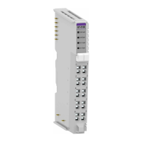
Communication between the RN series and the expansion module as well as system / field power supply of
the bus modules is carried out via the internal bus. It is comprised of 6 data pin and 2 field power pin.
Do not touch data and field power pins in order to avoid soiling and damage by
ESD noise.
*Please refer to the table below regarding the pin description from P1 to P8.
No.
Description
P1
Field Power (VCC)
P2
Field Power (GND)
P3
GBUS CLK
P4
GBUS MISO
P5
GBUS MOSI
P6
GBUS Token
P7
System Power (GND)
P8
System Power (VCC)

Questions and Answers:

Question and Answer IconNeed help?

Do you have a question about the CREVIS GT-5 Series and is the answer not in the manual?

CREVIS GT-5 Series Specifications

General IconGeneral
BrandCREVIS
ModelGT-5 Series
CategoryControl Unit
LanguageEnglish