i-module replacement Gasman
28
IX. i-module replacement
Installing or replacing an i-module
1. Ensure you are in a non-hazardous (safe) area, with suitable ESD
protection.
Switch off the unit
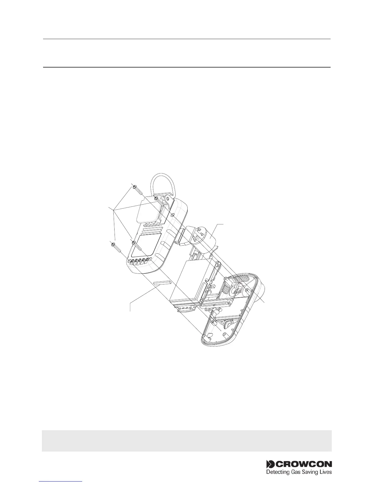
2. Remove the back cover by unscrewing the four M2.5, 12 mm Torx
(T6) screws as shown the in the drawing, point . Do not touch
the charging elastomer connector with your fingers.
3. Place the Gasman unit face down on a surface.
4. Unclipthei-modulefromitsretainingsupportclip.Easeonesideout
at a time. Ensure the elastomer which is retained within the body of
the support clip remains in place and should not be touched by hand.
5. Unwrapthereplacementi-modulefromanypackagingandensure
the sensor is fully seated on the module board.
i-module
Elastomer
If replacing an i-module with one of the same type, instrument specific configuration will be
retained. If replacing with a different i-module its default configuration will be loaded.