Com-Tech 1600 Amplifier Service Manual
13
Test 4: AC Power Draw
Spec: 80 Watts maximum quiescent.
Initial Conditions: Controls per standard.
Procedure: With no input signal and no load, measure
AC line wattage draw. If current draw is excessive,
check for high AC line voltage or high bias voltage.
Test 5: Common Mode Rejection
Spec at 100 Hz: –70 dB.
Spec at 20 kHz: –50 dB.
Initial Conditions: Controls per standard.
Procedure: No load. Inject a 0 dBu (.775VRMS) 100 Hz
sine wave into each channel, one channel at a time,
with inverting and non-inverting inputs shorted to-
gether. At the output measure less than –44 dBu
(4.9mVRMS). Inject a 0 dBu 20 kHz sine wave into
each channel, one channel at a time, with inverting and
non-inverting inputs shorted together. At the output
measure less than –24 dBu (49mVRMS). For Main
Modules with board numbers lower than D 7993-5
adjust N100 and N200 to calibrate CMR. For Main
Modules with board number D 7993-5 or greater
adjust R921 and R1021.
Test 6: Voltage Gain
Spec 26dB Gain: Gain of 20.0 ±3%.
Spec 0.775V 8/4 ohm Sensitivity: ±6%.
Spec 0.775V 70-V Sensitivity: ±6%.
Initial Conditions: Controls per standard.
Procedure: No load connected. Inject a 0.775 VAC 1
kHz sine wave with the Sensitivity Switch in the 26 dB
position. Measure 15.5 VAC ±0.5 VAC at the amplifier
output. Inject a 0.775 VAC 1 kHz sine wave with the
Sensitivity Switch in the 0.775V 8/4 ohm position.
Measure 65.7 VAC ±3.9 VAC at the amplifier output.
Inject a 0.775 VAC 1 kHz sine wave with the Sensitivity
Switch in the 0.775 VAC 70-V position and the Output
Mode Switch in the 70-V position. Measure 70.7 VAC
±4.2 VAC at the amplifier output. Return the Sensitivity
Switch to the 26 dB position. Return the Output Mode
Switches to the 8/4 ohm position.
Test 7: Phase Response
Spec: ±10° from 10 Hz to 20 kHz at 1 Watt.
Initial Conditions: Controls per standard, 8 ohm load on
each channel.
Procedure: Inject a 1 kHz sine wave and adjust for 1
watt output (2.8 VAC). Check input and output signals
against each other, input and output signals must be
within 10° of each other.
Electrical Checkout Procedures
Test 8: Level Controls
Spec: Level controlled by level controls.
Initial Conditions: Controls per standard.
Procedure: No load. Inject a 1 kHz sine wave. With level
controls fully clockwise you should see full gain. As
controls are rotated counterclockwise, observe simi-
lar gain reduction in each channel. When complete,
return level controls to fully clockwise position.
Test 9: Current Limit
Spec: Current Limit at 39 Amps, ±6 Amps.
Initial Conditions: Controls per standard.
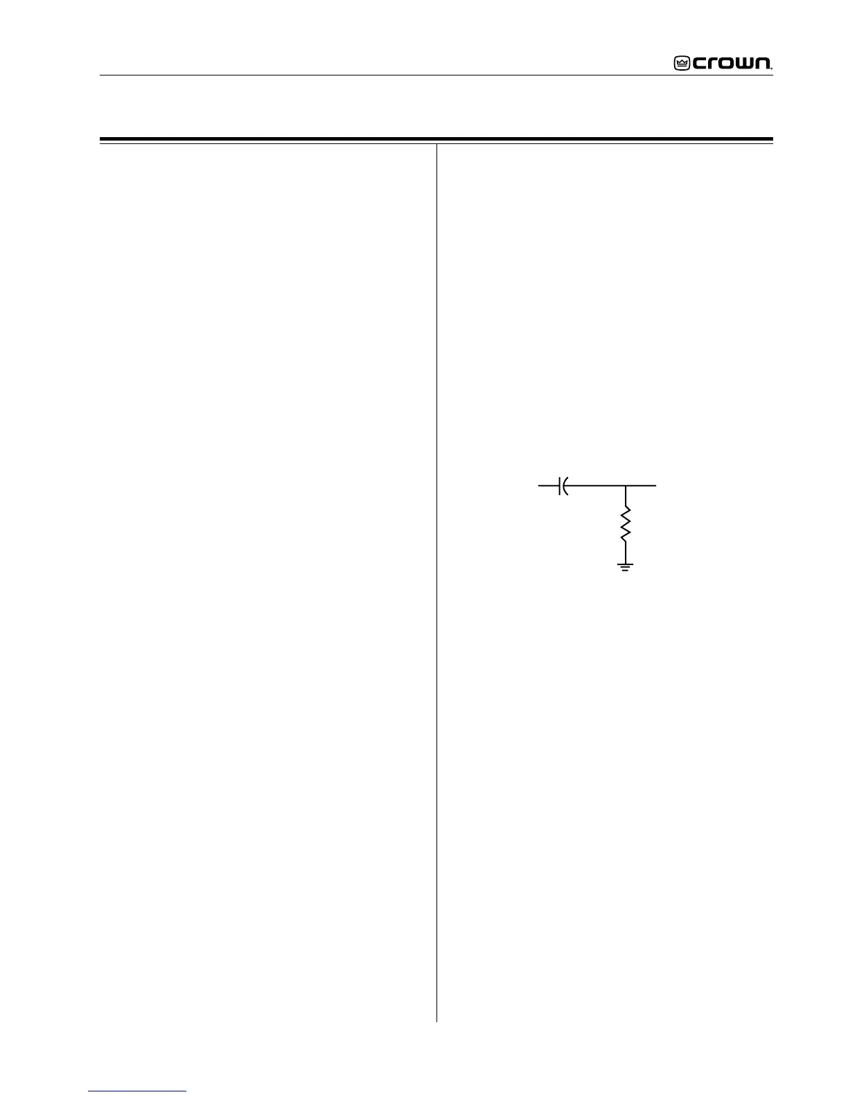
Procedure: Load each channel to 1 ohm. Inject a 1 kHz
differentiated (or 10% duty cycle) square wave. See
figure 4. Increase output level until current limit oc-
curs. Current limit should occur at 39 ±6 Amps (39
Vpk). Observe clean (no oscillations) current clipping.
Test 10: Slew Rate & 10 KHz Square Wave
Spec: 17 - 25 V/µS, 8 ohm load.
Initial Conditions: Controls per standard.
Procedure: Load each channel to 8 ohms. Inject a 10
kHz square wave to obtain 35 Volts zero-to-peak at
each output. Observe the slope of the square wave. It
should typically measure 17-25 V/µS. Also, the square
wave must not include overshoot, ringing, or any type
of oscillation.
Test 11: Crosstalk
Spec: -60 dB at 20 kHz.
Initial Conditions: Controls per standard. Terminate
input of channel not driven with 600 ohms.
Procedure: 8 ohm load on each channel. Inject a 20 kHz
sine wave into the channel 1 input and increase output
level to 64 VAC. Measure less than 64 mVAC at the
output of channel 2. Inject a 20 kHz sine wave into the
channel 2 input and increase output level to 64 VAC.
Measure less than 64 mVAC at the output of Ch 1.
In
Out
.047 uF
1K Ohm
Figure 4. Differentiator Circuit