I-Tech HD DriveCore Series Power Ampliers
Operation Manual
page 61
16.7 Polar Lobing Error
Polar lobing is a potential problem when spatially separated
non-coincident drivers are crossed over. Throug the crossover region
both drivers are radiating simultaneously. This may cause a narrowing
of the coverage pattern and the creation of a directional lobe. It is very
desirable that this lobe face straight ahead, and not directionally
wander with frequency. If it does, lobing error occurs.
Polar lobing error is minimized when the low- and high-pass sections
of the crossover are in-phase with each other throughout the crossover
are in-phase with each other throughout the crossover region. This is
an attribute of the “Linquitz-Riley” (LR) type of crossover rewponses.
Polar lobing can also be minimized by reducing the crossover overlap
with zero-phase sharp-cutoff filters such as provided by FIR filters.
16.8 Crown’s Implementation of FIR Filters
Crown’s FIR filter implementation uses state-of-the-art digital signal
processing techniques which are highly optimized for the DSP engine
in the I-Tech HD series of amplifiers.
16.9 FFT Convolution
The resource requirements of a high-performance FIR filter in terms of
cpu cycles per sample, datapath bandwidth and memory footprint can
exceed those of an IIR solution by several orders of magnitude. Key to
an efficient FIR implementation is the use of Fast Fourier Transform
(FFT) techniques to accelerate the FIR convolution process, which is
usually thought of as a time domain operation. Time domain
convolution is something to be avoided, because it is extremely
expensive in the computational sense. Fortunately, signal processing
theory tells us that multiplication in the frequency domain is equivalent
of convolution in the time domain. This is important because
multiplication is very efficient in comparison to convolution. Of course,
an efficient and speedy means of moving between the time and
frequency domains is also required. This is where the FFT comes in.
Using the FFT to transform back and forth between the time and
frequency domains so as to replace convolution with multiplication is
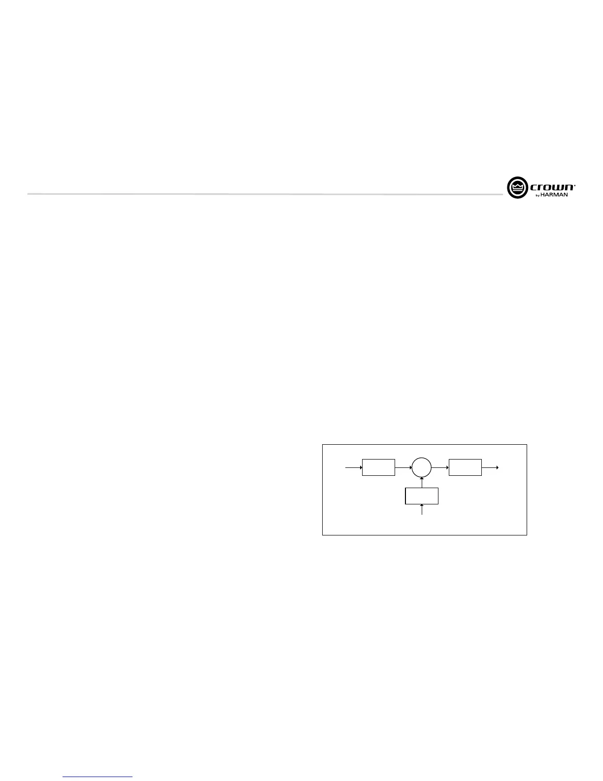
referred to as FFT Convolution. Figure 16.2 shows a block diagram of
the FFT convolution process.
Fig. 16.2 FFT conbolution block diagram. here the input and filter
impulse responses are both individually FFT’d and multiplied and then
inverse FFT’d to genterate the output.
16 Application of FIR Filters to Loudspeaker Crossovers
16.5 High Rolloff and Steep Slopes
FIR filters can be designed to have extremely high stop-band rolloffs
and exceptionally steep slopes which greatly minimizes crossover
driver overlap. In a conventional analog or analog-based IIR crossover,
driver overlap can extend over two or three octaves. FIR crossovers
dramatically restrict the operating overlap bandwidth of the crossover
which considerable reducers the range over which both upper and
lower range drivers are radiating in the same frequency range. Very
narrow overlaps of one-third octave or less can be implemented with
FIR filters.
In addition, the extremely steep slopes of FIR filters offer greater driver
protection and reduced distortion. Beyond the driver’s linear frequency
range, energy is attenuated so rapidly that most non-linearity’s cease to
be a problem. The driver does not need to be as well behaved outsied
its frequency range. Power handling capability of HF drivers is much
improved. The narrower crossover region also lessens the need for
precise driver time alignment since the overlap region is so small.
16.6 Stop-band Attenuation
Associated with the very high stop-band rolloff of an FIR filter, is the
associated extremely high stop-band attenuation. This minimizes
interaction between adjacent drivers such as a low-frequency woofer
signal bleeding into a tweeter and thus causing intermodulation
distortion. In a home theater setup, high stop-band attenuation of the
subwoofer minimizes subjective localization of the woofers due to
hight-frequency bleed through.
input output
lter impulse response
FFT
FFT
X
inv FFT
 Loading...