2–14
FM30/FM100/FM250 User's Manual
2.11Program Input Fault Time-out
You can enable an automatic turn-off of the carrier in the event of program failure.
To enable this option, see illustration 2-17 on page 2-15. The time between program
failure and carrier turn-off is set by a jumper (JP1) on the voltage regulator board
(see page 6–17 for board location). Jumper pins 1 and 2 (the two pins closest
to the edge of the board) for a delay of approximately 30 seconds; pins 3 and 4 for a
2–minute delay; pins 5 and 6 for a 4–minute delay, and pins 7 and 8 for an 8–
minute delay.
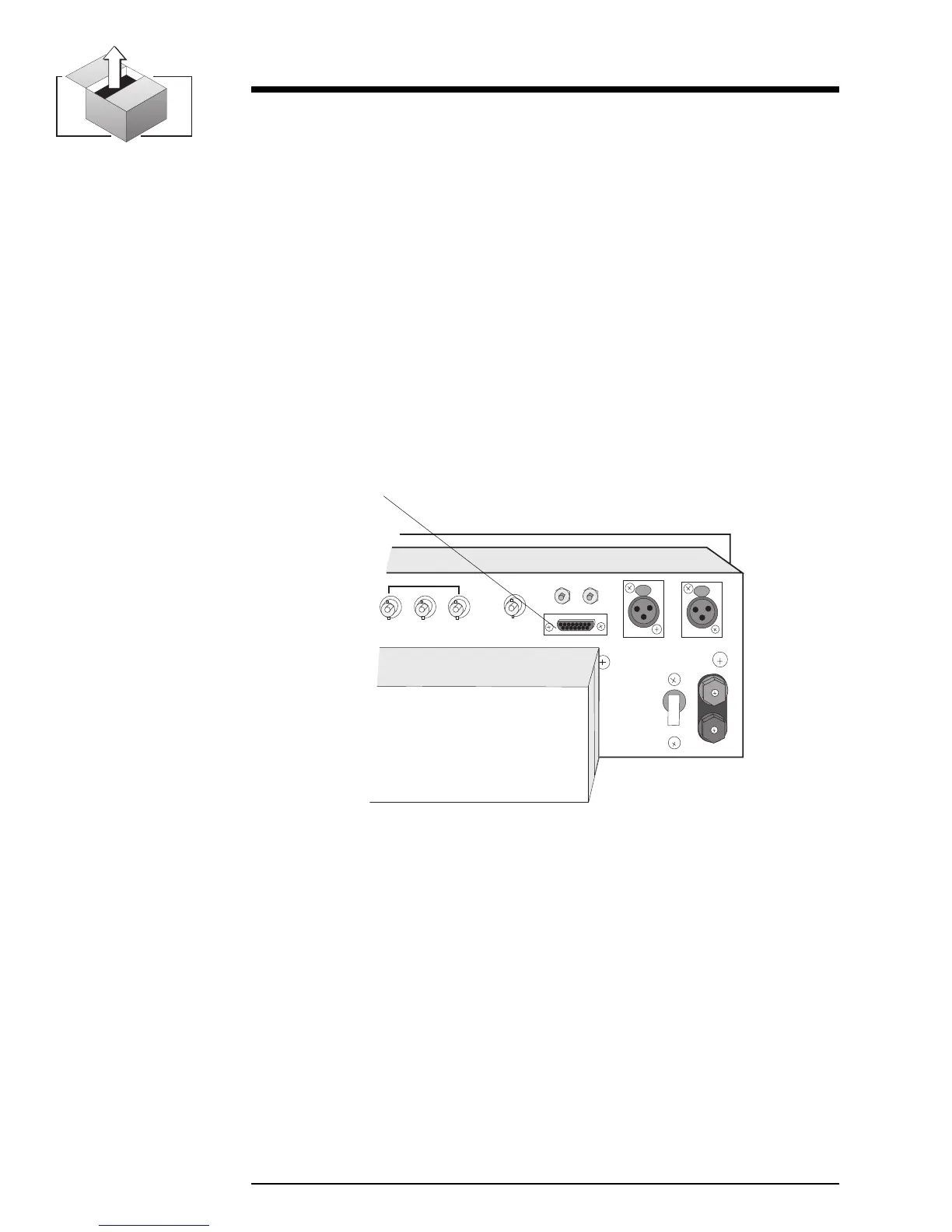
2.12 Remote I/O Connector
Remote control and remote metering of the transmitter is made possible through a
15–pin, D-sub connector on the rear panel. (No connections are required for
normal operation.)
Illustration 2–16 Remote I/O Connector
OFF
SCA IN
COMPOSITE IN
MONITOR
R
L
23
REMOTE I/O
RIGHT
LEFT/MONO
B
A
T
T
E
R
Y
36 VDC
+
–
CIRCUIT
BREAKER
1
Remote I/O
Illustration 2-17 on page 2-15 summarizes the Remote I/O pin connections.