3–4
FM30/100/250 User's Manual
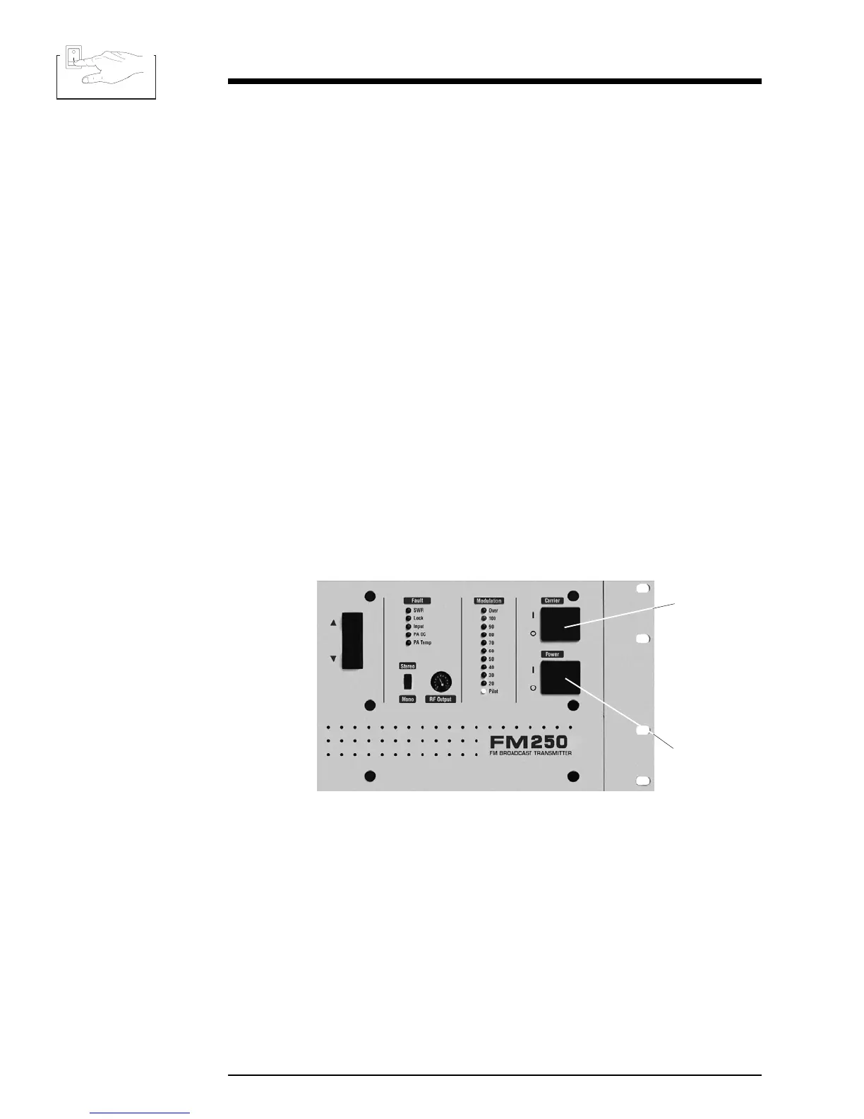
3.2 Power Switches
3.2.1 DC Breaker
The DC breaker, on the rear panel, must be on (up) for transmitter operation, even
when using AC power. Electrically, the DC breaker is located immediately after
diodes which isolate the DC and AC power supplies.
3.2.2 Power Switch
The main on/off power switch controls both the 120/240 VAC and the DC battery
power input.
3.2.3 Carrier Switch
This switch controls power to the RF amplifiers and supplies a logic high to the
voltage regulator board, which enables the supply for the RF driver. In addition,
the Carrier Switch controls the operating voltage needed by the switching power
regulator.
A "Lock Fault" or a low pin 12 (/Carrier Off) on the Remote I/O connector will hold
the carrier off. (See section 2.12.)
Illustration 3–3 Front Panel Power Switches
Main Power
Switch
Carrier
Switch