4–15
Principles of Operation
®
FM250
4.15 Receiver Circuit Board Option
This option allows the transmitter to be used as a translator. The receiver board
receives terrestrially fed RF signal and converts it to composite audio which is then
fed into the exciter board. Microprocessor controlled phase lock loop technology
ensures the received frequency will not drift, and multiple IF stages ensure high
adjacent channel rejection. Refer to illustrations 4–6, 6–16 and its schematic for
the following discussion.
The square shaped metal can located on the left side of the receiver board is the
tuner module. The incoming RF signal enters through the BNC connector (top
left corner) and is tuned through the tuner module. Input attenuation is possible
with jumper J1 on the top left corner of the receiver board. Very strong signals
can be attenuated 20 dB automatically by placing the jumper on the left two pins
(“LO” position). An additional 20 dB attenuation is also available with the jumpers
in the top left corner of the board. The frequencies are tuned by setting switches
SW1 and SW2 (upper right corner). These two switches are read upon power up
by the microprocessor (U4). The microprocessor then tunes the synthesizer IC
MC145170 (U3) to the selected frequency. The switches frequency range is 87.9
Mhz at setting “00” to 107.9 Mhz at setting “64”. Other custom ranges are available.
The synthesizer chip works on a phase lock loop system. It receives the frequency
information from pin 6 of the tuner module, then goes through a FET buffer
amplifier (Q2) on its way to synthesizer IC (U3). The synthesizer feeds back a DC
voltage through two resistors to pin 4 of the tuner module. Different frequencies
cause different tuning voltages to go to the tuner module to tune it on frequency.
The frequency synthesizer locks on to the exact frequency needed and adjusts the
DC voltage accordingly. The microprocessor tunes the frequencies of the
synthesizer IC, but the DC tuning voltage is somewhat dependent on the tuner
module.
Generally, the voltage is around 0.5 volt DC for tuning 88.1 MHz, and from 5.5 to
6.5 volts DC for tuning 107.9 MHz. The 10.7 MHz IF frequency comes out of the
tuner module on pin 5 and is coupled into the first filter FL1; passes through FL1
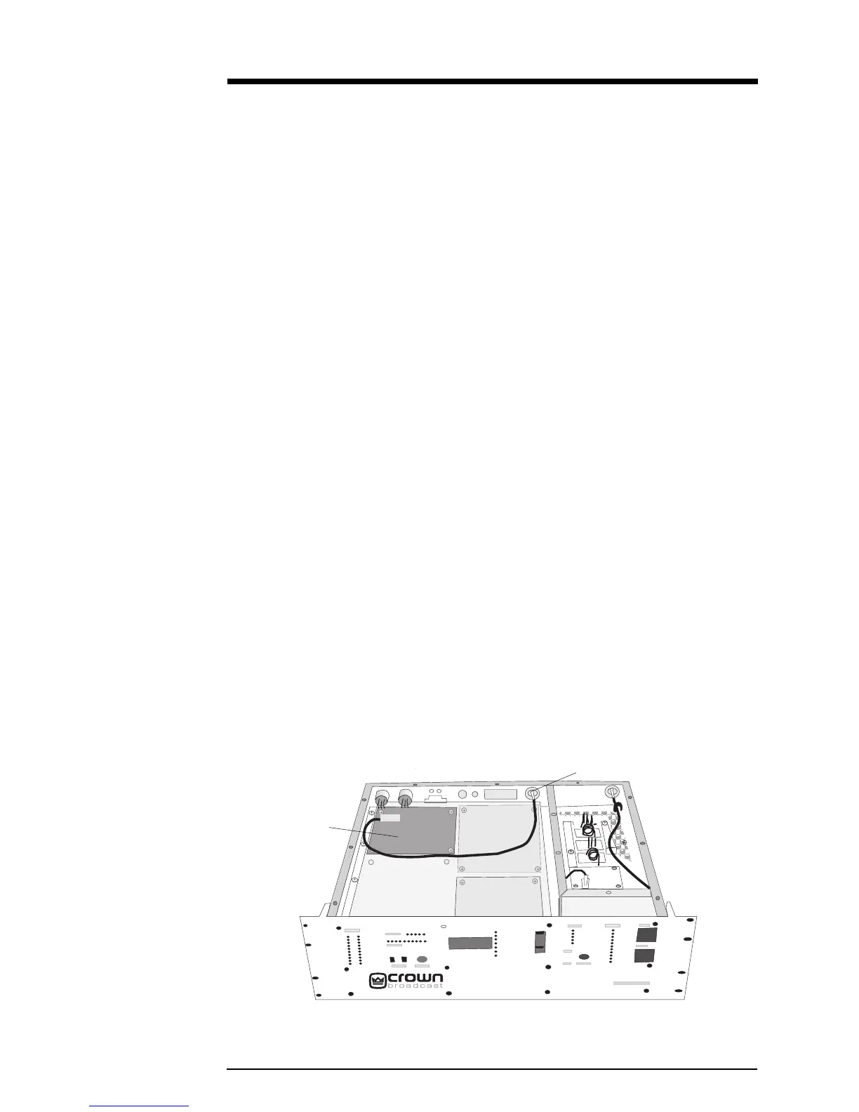
Receiver
Module
RF In
Illustration 4–6 Receiver Board
 Loading...