Macro-Tech 1200 Amplifier Service Manual
14
Test 6: Voltage Gain
Spec 26dB Gain: Gain of 20.0 ±3%.
Spec 0.775V Sensitivity: ±6%.
Spec 1.4V Sensitivity: +12%/–6%.
Initial Conditions: Controls per standard.
Procedure: No load connected. Inject a 0.775 VAC 1
kHz sine wave with the Sensitivity Switch in the 26 dB
position. Measure 15.5 VAC ±0.5 VAC at the amplifier
output. Inject a 0.775 VAC 1 kHz sine wave with the
Sensitivity Switch in the 0.775V position. Measure 50.6
VAC ±3 VAC at the amplifier output. Inject a 1.4 VAC
1 kHz sine wave with the Sensitivity Switch in the 1.4V
position. Measure 50.6 VAC +6/–3 VAC at the ampli-
fier output. Return the Sensitivity Switch to the 26 dB
position.
Test 7: Phase Response
Spec: ±10° from 10 Hz to 20 kHz at 1 Watt.
Initial Conditions: Controls per standard, 8 ohm load on
each channel.
Procedure: Inject a 1 kHz sine wave and adjust for 1
Watt output (2.8 VAC). Check input and output signals
against each other, input and output signals must be
within 10° of each other.
Test 8: Level Controls
Spec: Level controlled by level controls.
Initial Conditions: Controls per standard.
Procedure: No Load. Inject a 1 kHz sine wave. With
level controls fully clockwise you should see full gain.
As controls are rotated counterclockwise, observe
similar gain reduction in each channel. When com-
plete, return level controls to fully clockwise position.
Test 9: Current Limit
Spec: Current Limit at 30 Amps, ±2 Amps
Initial Conditions: Controls per standard.
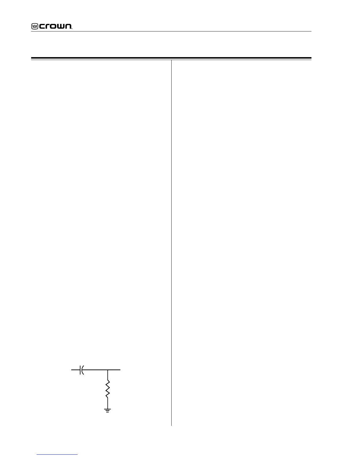
Procedure: Load each channel to 1 Ohm. Inject a 1 kHz
differentiated (or 10% duty cycle) square wave. See
figure 4. Increase output level until current limit oc-
curs. Current limit should occur at 30 ±2 Amps (30
Vpk). Observe clean (no oscillations) current clipping.
Electrical Checkout Procedures
Test 10: Slew Rate & 10 kHz Square Wave
Spec: 13 - 15 V/µS.
Initial Conditions: Controls per standard.
Procedure: Load each channel to 8 ohms. Inject a 10
kHz square wave to obtain 65 volts zero-to-peak at
each output. Observe the slope of the square wave. It
should typically measure 13 to 15 V/µS. Also, the
square wave must not include overshoot, ringing, or
any type of oscillation.
Test 11: Crosstalk
Spec: -60dB at 20 kHz.
Initial Conditions: Controls per standard. Terminate
input of channel not driven with 600 ohms.
Procedure: 8 ohm load on each channel. Inject a 20 kHz
sine wave into the Channel 1 input and increase output
level to 33 VAC. Measure less than 33 mVAC at the
output of Channel 2. Inject a 20 kHz sine wave into the
Channel 2 input and increase output level to 33 VAC.
Measure less than 33 mVAC at the output of Channel
1.
Test 12: Output Power
Spec at 8 Ohm Stereo: >= 320W at 0.1% THD.
Spec at 4 Ohm Stereo: >= 470W at 0.1% THD.
Spec at 2 Ohm Stereo: >= 600W at 0.1% THD.
International 8 Ohm Stereo: >=305W at 0.1% THD.
International 4 Ohm Stereo: >=430W at 0.1% THD.
International 2 Ohm Stereo: >=535W at 0.1% THD.
Initial Conditions: Controls per standard.
Procedure: Load each channel to 8 ohms. Inject a 1 kHz
sine wave and measure at least 50.6 VAC at the output
of each channel. Load each channel to 4 ohms. Inject
a 1 kHz sine wave and measure at least 43.36 VAC.
Load each channel to 2 ohms. Inject a 1 kHz sine wave
and measure at least 34.64 VAC. All power measure-
ments must be at less than 0.1% THD.
Test 13: Reactive Loads
Spec: No oscillations. Safe with all types of loads.
Initial Conditions: Controls per standard.
Procedure Capacitive: Load each channel to 8 ohms in
parallel with 2 µF. Inject a 20 kHz sine wave with 33
VAC output for 10 seconds.
Procedure Inductive: Load each channel to 8 ohms in
parallel with 159 µHenries. Inject a 1 kHz sine wave
with 20 VAC output for 10 seconds.
Procedure Torture: Load each channel with the primary
(red and black leads) of a DC-300A transformer (D
5781-6). Inject a 15 Hz sine wave at sufficient output
level to cause 3 to 5 flyback pulses, for 10 seconds.
In
Out
.047 uF
1K Ohm
Figure 4. Differentiator Circuit
 Loading...