61
L510032-16
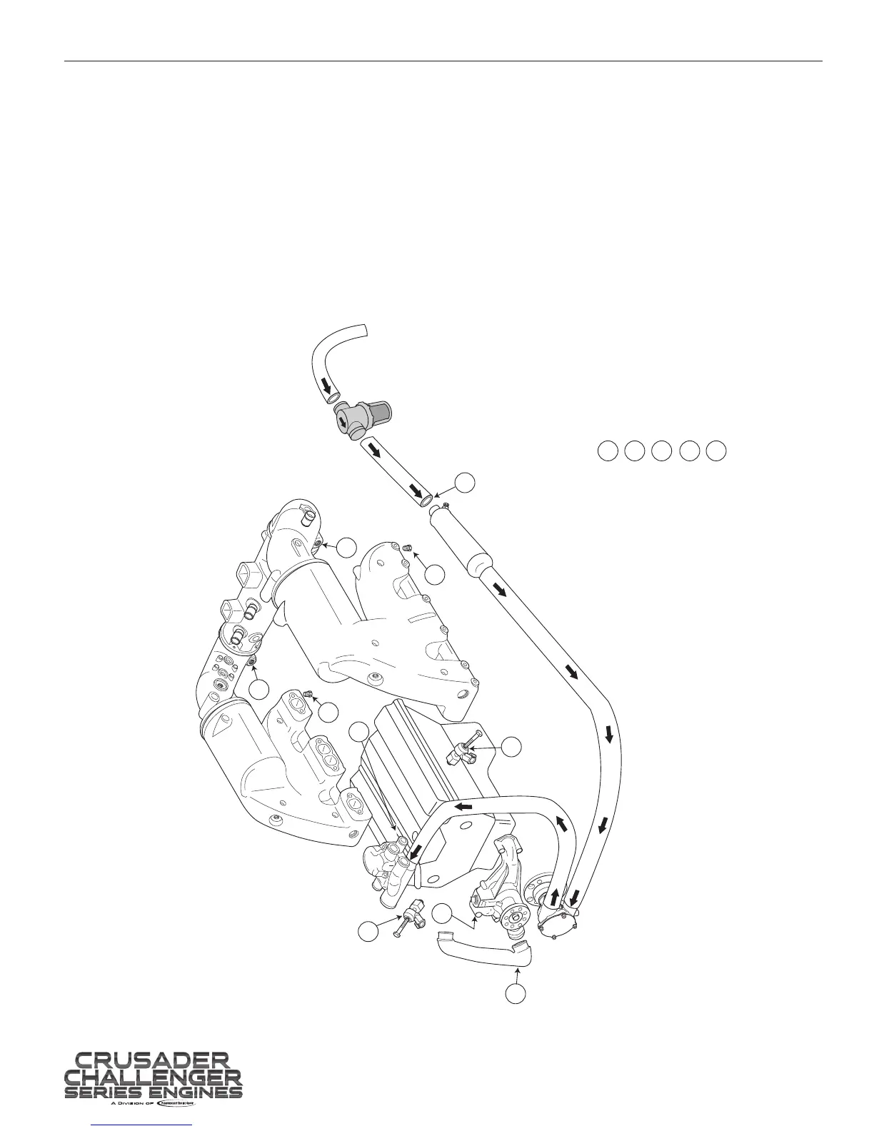
WATER FLOW DIAGRAMS - 15
Figure 15-1 5.7L CES DDrive Crusader Challenger
A
Note: This diagram is for illustration purposes
only. The actual routing and/or shape of the hoses
may vary slightly depending on installation.
1
1
2
3
3
4
5
5
B
(If Equipped) Remove heater hoses from locations A and B.
CAUTION: If compressed air is used to purge Heater, use no
more than 10psi. The heater core can be damaged from
excessive air pressure.
1
2
3
4
5
Drain Locations
- Engine Block Drains - Remove Knock Sensors
- Engine Circulating Water Pump Hose - Remove Hose to Drain
- Exhaust Manifolds - Remove Drain Plugs
- Transmission Cooler - Remove Inlet Hose
- Exhaust System Corners - Remove Drain Plug
 Loading...